A primer and a new product announcement
Numerous industry problems were addressed with the emergence of Dry Low NOx (DLN) and Dry Low Emissions (DLE) gas turbine combustion designs in the 1990s. Dramatic improvements were realized over so-called Wet Low Emissions (WLE) approaches: not only were emissions reduced far more under DLE/DLN than under WLE strategies, but operations incorporating gas turbines were also able to use considerably less water. Unfortunately, however, those improvements came at a cost: damaging pressure pulsations within the combustor and the havoc these wreaked if not detected and abated. Consider this excerpt from a 2004 Power Engineering article[1], succinctly summarizing the situation:
“…the lean-burning DLN combustors are prone to flame instability, which can cause pressure pulsations large enough to destroy the combustor, launching debris downstream where it annihilates other hot-gas-path components. To detect and correct flame instability before it causes millions of dollars of turbine damage, savvy users have begun to install advanced sensors and robust software that monitor the combustor dynamics in real time.”
Vibro-meter products were at the forefront of those so-called “savvy users” with our portfolio of high-temperature pressure sensors and know-how for combustion dynamics monitoring. And the reason we were there from the very beginning was quite simple: we had already been building high-temperature accelerometers for extreme environments for decades, and the technology to develop dynamic pressure sensors is nearly identical to that of accelerometers. It was indeed a very small jump from extreme environment accelerometers to extreme environment pressure sensors. Not surprisingly, customers and turbine OEMs turned to us very early on for solutions and we were thus among not just the earliest providers in this space, but also the most successful and the most trusted.
In the intervening three decades, we have steadily improved and broadened our piezoelectric pressure sensing offerings to reach higher temperatures, address ever-tighter constraints of confined mounting spaces, and deliver better performance. We have also worked to ensure that our portfolio breadth means you can right-size the sensor you need by balancing cost and performance, paying for only what you need in terms of maximum temperature, maximum pressure, sensitivity, structural acceleration compensation, and other specifications.
But how exactly does a piezoelectric pressure sensor work – and why the need for yet another addition to the portfolio: our all-new CP751?
In this article, we provide a basic tutorial on piezoelectric pressure sensors that will be helpful for anyone working with these devices. We close by introducing our new CP751 – the latest addition to our dynamic pressure sensing portfolio.
The Piezoelectric Effect
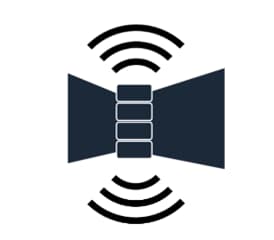
The fundamental principle of a piezoelectric material is that if you apply force to it – whether by compressing it / stretching it, or orienting the forces in either a shearing direction or transverse direction – this force will disrupt the distribution of charge within the material and it will become polarized. And when you remove the force, the charge will resume its initial state. This charge can be measured and is directly proportional to the force applied. We can thus use piezoelectric devices to measure dynamic force. In fact, piezoelectric transducers such as accelerometers are fundamentally force transducers. We obtain acceleration merely by application of Newton’s Second Law: Force (F) = Mass (M) x Acceleration (A). Since we can know the force by measuring the electrical charge, we can simply divide by the known mass on which the measured force is acting.
Figure 1: When we alternately place a piezoelectric material into compression and tension, it produces a changing electrical charge (Q) that we can measure. This occurs because the equal distribution of charges in the natural state of the material is altered and it becomes polarized. Here we are squeezing the piezoelectric material in so-called compression mode; i.e., in line with the cylinder’s axis. If we were to instead introduce transverse forces (i.e., squeezing perpendicular to the cylinder’s axis along its “waist”) or shearing forces (opposing forces acting in a way that tries to cut the cylinder in half), these would likewise result in a changing charge based on the material’s piezoelectric properties.
Measuring Pressure
Pressure is simply the total force divided by the area over which it acts. For example, 20 pounds of force distributed over an area of 20 square inches results in a pressure of 1 pound per square inch (psi). Thus, if we know the force (by measuring it) and we know the area over which it acts, we can know the pressure. This is the fundamental premise of a piezoelectric pressure transducer: we measure force using an accelerometer and divide by the area over which it acts.
Consider the disc-shaped, flexible diaphragm of area A depicted in Figure 2. If we allow pressure P to act on the diaphragm, the force is simply the pressure times the area of the diaphragm. Since we know the area, and since we can precisely measure the dynamic force with our piezoelectric material, we know the pressure. In the case of combustion dynamics measurement, these forces are in the form of dynamic pressure pulsations.
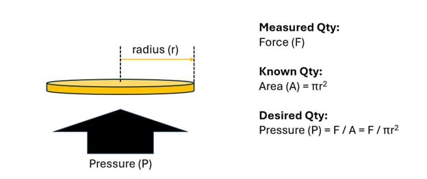
Figure 2: A flexible, disc-shaped diaphragm can be used in conjunction with a piezoelectric crystal to measure pressure. The pressure acting on the diaphragm at any given moment is simply the instantaneous force divided by the diaphragm’s area.
Figure 3 depicts the basic operation of a piezoelectric pressure sensor. We allow pressure to impinge on a flexible diaphragm. The forces acting on the diaphragm as a result of this pressure are transferred directly to a piezoelectric crystal which is in compression mode and alternately squeezed and relaxed. We then convert the force measured by our piezoelectric crystal to a pressure reading by dividing by the diaphragm’s area.
Figure 3: In a piezoelectric pressure sensor, dynamic pressure waves impinge on a flexible diaphragm. The diaphragm vibrates as a result of these dynamic pressure pulsations, alternatively squeezing and relaxing a piezoelectric crystal. The dynamically changing charge produced is directly proportional to the dynamically changing force and the pressure becomes simply this force divided by the diaphragm’s area as shown in Figure 2.
Challenges

Although the principles of operation are simple enough, as with most things in life “the devil is in the details”. Building a robust piezoelectric pressure sensor that maintains accuracy at elevated temperatures, will not wear out over billions of pressure pulsation cycles, and does not exhibit large inaccuracies due to structural vibration, is the result of many years of refinement by the vibro-meter team and our accumulation of domain knowledge. Below, we list six areas that will aid you in understanding why these sensors are far from commodity devices.
1. Structural Vibration Errors
Let’s first consider that the vibrating diaphragm of figure 3 is not the only excitation acting on our piezoelectric crystal. If the entire sensor structure is vibrating – as it often is – this will impart acceleration forces on the crystal which will mistakenly be interpreted as pressure pulsations. The actual charge emanating from the crystal is the superposition of all excitations, whether from the moving diaphragm, structural vibration, thermal effects, etc. In some situations, a pressure sensor is sufficiently removed from structural vibration effects that any residual vibration acting on the sensor is negligible and no special compensation is necessary. In many situations, however, compensation is necessary. One approach is to introduce a second piezoelectric crystal “stack” that generates a structural vibration signal, but to reverse its polarity and combine it with the signal from the primary crystal stack; i.e., the stack with which we are measuring pressure. This effectively subtracts out or cancels the structural acceleration. The benefit is that this is a very effective compensation mechanism. However, it introduces the complexity of a second crystal stack into our sensor, and thus not only its size, but its cost. In some cases, this additional cost is warranted and can be justified for the application.
In other cases, a less expensive but sufficiently effective compensation method is desirable. Vibro-meter was a pioneer in this area with a patented[2] method that can adequately compensate for structural vibration in many cases, but without introducing the costs of a second crystal stack.
2. Thermal Effects

As can be imagined, building a sensor with a very sensitive piezoelectric crystal inside means that the only forces acting on the crystal are the intended forces. As we described a moment ago, structural acceleration forces are undesirable and need to be either minimized or compensated for in some fashion.
Another area in which forces can act on the crystal arises from thermal expansion of the sensor’s case and various components. As the sensor expands and contracts under various temperature gradients, if the case does not grow uniformly, this can introduce unintended forces on the crystal which will result in erroneous readings. The manufacturing techniques and processes used to minimize such effects are generally proprietary. Suffice to say that these are very important considerations and require a provider that has substantial experiencing in designing and building sensors for extreme temperature environments. This is true not only for the upper range of temperatures – today around 700° C, but also at the lower end when sensors must be used in cryogenic applications.
3. Triboelectric Effects

Because the level of electrical charge provided by piezoelectric sensors is quite small – typically in picocoulombs – any other sources of charge disturbance in the measurement chain must be minimized. This includes cables and connections between the sensor and its charge amplifier, which converts the dynamically changing charge to a dynamically changing current[3]. While the output of the charge amplifier – such as our IPC707 – is not subject to further disturbances in charge, this is not true at the input to the charge amplifier. Triboelectric effects in cables and connectors must be minimized and vibro-meter has substantial experience in not only engineering connectors and cables, but installing them properly to minimize such effects.
4. Crystal Sources

The most common natural crystal used in piezoelectric sensors is tourmaline and it has several advantages, including the simplicity of its piezoelectric lattice properties compared to other man-made piezoelectric crystal materials.
A disadvantage of tourmaline, however, is that the crystal can have impurities and it can be more difficult to thus find suitable parts of the crystal when cutting it into wafers and other geometries used in sensors. The supply chain for tourmaline, as a natural material, can also present challenges that are not intrinsic to man-made materials.
Man-made materials, on the other hand, often present less-problematic supply chain issues and as crystals that are grown in a lab similar to the way semi-conductor ingots are grown, there are fewer impurities and thus higher yields and more consistent ability to harvest wafers and other geometries. However, the piezoelectric properties of man-made crystals are frequently more complicated in terms of the 3-dimensional lattice structure and thus cross-axis effects that must be accounted for. There are thus pros and cons to both natural and man-made piezoelectric materials and the decision to use one or the other is rarely born simply out of a single criterion. Vibro-meter’s CP-series pressure sensors and CE/CA series accelerometers[4] reflect a mix of both natural and man-made crystals.
5. Curie Temperature
The Curie Temperature is a point above which the piezoelectric properties of a material cease to manifest. Also, when the material exceeds its Curie Temperature, its piezoelectric properties are not just temporarily suppressed – they are largely lost forever and cannot be restored simply by lowering the temperature below the Curie Point. Although some piezoelectric properties will return, the permanent degradation is on the order of 90% and effectively renders the crystal useless. For this reason, a wide safety margin is always employed to ensure a sensor is never forced to operate close to its Curie Temperature. However, the Curie Temperature is rarely the limiting factor in a sensor’s temperature performance. It is instead the manufacturing complexities of combining a high-temperature crystal into a case that will be highly stable over temperature. Although it is possible to develop sensors that go above 700° C, and this is not necessarily a threshold established by the physics of the materials themselves, the complexities of manufacturing such sensors mean that the costs rise somewhat exponentially, and the benefits of higher temperature operation would not necessarily outweigh the increased costs.
6. Resistivity
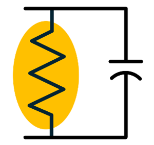
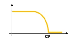
A particularly important aspect of high-temperature operation for piezoelectric crystals is that their resistance begins dropping dramatically as the temperature rises. A discussion of charge amplifiers is beyond the scope of this article, but suffice to say that when resistance of the piezoelectric material becomes too small, the signal-to-noise ratio of the sensor becomes likewise too small at low frequencies due to the effect of an R-C (resistance-capacitance) time constant in the circuit composed of the sensor’s crystal and its accompanying charge amplifier. Because this manifests as an increasingly large time-constant in the circuit, it means that at high temperatures, the signal-to-noise ratio for low frequencies is greatly affected and degrades significantly. Piezoelectric sensors are thus only marginally useful for detecting conditions such as so-called Lean Blowout (LBO) as well as flashback and flame-out that typically manifest at low frequencies. Other technologies – such as optical[5] – can be better choices in such situations due to their ability to deliver adequate low-frequency signal-to-noise ratios in high-temperature environments. This is sometimes referred to as the “blind zone” for piezoelectric sensors. This could be somewhat of a misnomer because although their ability to “see” low frequencies at high temperatures is diminished, it is not entirely absent – it is merely swamped by the noise generated under such low resistivities and the corresponding effects on the circuit.
The above six points, of course, are not an exhaustive list of all the nuances and challenges inherent in building a high-temperature piezoelectric pressure sensor, but they do provide a framework in which to understand that the sensors are far from commodity-level devices. Indeed, building a sensor that works at 120° C bears very little resemblance to the intricacies of building a sensor that works at 700° C.
The all-new CP751
Some of the most desirable qualities in a dynamic pressure transducer for combustion dynamics monitoring are as follows:
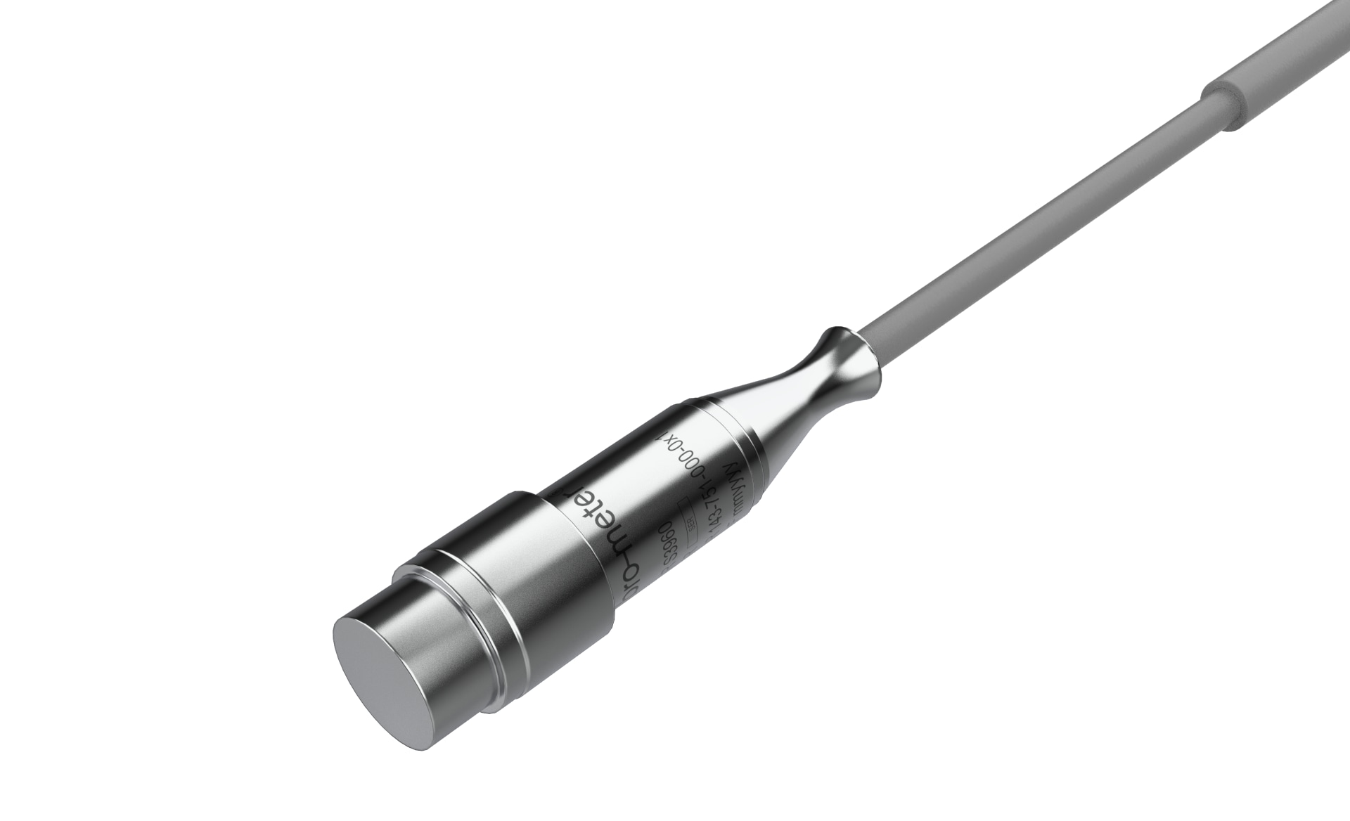
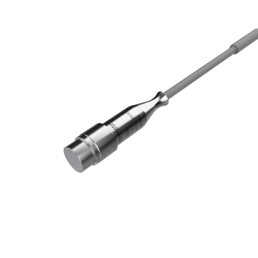
The CP751 embodies all of these qualities and delivers the smallest of packages in our CP-series offerings, measuring just 11mm in diameter at its widest part. This compact size allows it to be used in places other sensors cannot reach – such as routing through tubes where necessary to closely observe combustors.
The sensor can also be used in continuous operation at temperatures up to 700° C meaning that tradeoffs generally do not have to be made by mounting the sensor further from the flame where the pressure pulsations may generally be weaker.
The sensor also features a robust 120 pC/bar output sensitivity that is stronger than its predecessor, the CP500-series. It is also 5 times stronger than our other 11mm pressure sensor, the CP211.
Other salient features of the new CP751 include:
You can learn more about the CP751 in the product datasheet. You can learn about all of the other CP-series offerings by visiting our dynamic pressure sensor page or contacting your nearest vibro-meter representative.
Editor’s Note:
Readers wanting to know more about piezoelectric sensors are encouraged to visit f3lix-tutorial.com. There you will find numerous animations and other valuable resources to help you better understand how piezoelectric sensors are constructed, how piezoelectricity works at a more detailed level, and additional related topics. The website and its content were developed by Mr. Felix Schmid, vibro-meter’s Head of Engineering until his retirement in 2015. Felix holds numerous patents and is regarded globally as a subject matter expert on the topics discussed in his tutorial.
[1] Swanekamp, R. “Gas Turbines – On-Line Monitoring Systems Help Silence Combustor Humming” Power Engineering Magazine, Vol 108, Issue 5, May 2004
[2] US Patent 6513387B1, ”Acceleration compensated pressure measuring instrument”. 4 Feb 2003. Schmid, F. Vibro Meter SA.
[3] Vibro-meter charge amplifiers such as the IPC707 can be configured for either a current output or a voltage output, ensuring compatibility with a wide variety of combustion dynamics monitors.
[4] Selected vibro-meter accelerometers use piezoelectric ceramic elements such as lead zirconium titanate (PZT) rather than crystals. Ceramics are generally reserved for our lower-cost offerings that are not intended for extreme environments.
[5] Vibro-meter is involved in pioneering work with optical dynamic pressure sensing. We will be sharing more about this game-changing technology and the applications for which it is particularly well-suited in the coming months.