Humorist and author Mark Twain famously quipped “the report of my death was an exaggeration1” In like manner, dire predictions anticipating the demise of stand-alone vibration monitors have been ongoing for decades. Will rack-based monitors be swallowed up and made obsolete by tightly integrated PLC or DCS modules? What are the advantages of stand-alone systems and why have they persisted for so long? Are integrated systems even allowed under popular industry standards – and if so, under what constraints? Are some integration methods inherently better than others for customers? For suppliers? Keep reading to learn the answers.
Introduction
For decades now, there has been an almost irresistible urge for control system manufacturers to develop highly specialized cards for their control systems that go beyond the usual complement of Proportional-Integral-Derivative (PID) and so-called “ladder logic” on/off control for analog inputs, analog outputs, discrete inputs, and discrete outputs. Whether Programmable Logic Controller (PLC) manufacturers, Distributed Control System (DCS) manufacturers, or turbine control manufacturers, it is not unusual to find their catalogs contain vibration monitoring cards, surge control cards, tachometers, process weighing cards, and other specialized cards designed to use their chassis, their backplanes, and their proprietary communications. It is also becoming common to find so-called “remote I/O” form factors that don’t insert into a conventional chassis and instead “live on the skid” where all the instrumentation can be self-contained with the machine package and a single (or redundant) cable can carry everything back to the control room and “brain” of the control system. We will examine both approaches in this article as well as solutions like vibration transmitters and conventional stand-alone rack-based systems. As we will see, all have their place, and none will become obsolete or crowded out by the others anytime soon.
History
Continuous vibration monitoring systems trace their roots to the late 1950s and early 1960s. Many of the earliest adopters of these systems were not end users per se but rather machinery OEMs that saw the value of continuous monitoring. As end users in turn began to adopt these systems and insist on their inclusion from the OEM each time they purchased a new machine, an interesting but predictable sequence of events occurred. The OEM wanted to get in on the action – not just by passing along the vibration monitors from a third-party supplier such as vibro-meter but by replicating the functionality in their own control system modules. As a result, a dozen or more such solutions arose between 1970 and 2000. Figure 1 shows merely three such examples among many that could be cited.
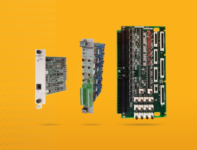
Figure 1: Form-factor integration of vibration monitoring modules that conform to the OEM’s control system. (L to R) Elsag-Bailey (now ABB) and its CMM11 condition monitoring module, Dresser-Rand with a 6-channel (+ phase) filtered vibration module, and GE with a 14-channel (incl. phase) universal TVIB vibration module. All of these modules are more than 20 years old and now largely or fully obsolete.
Control of machines is a high-stakes business, with millions of dollars of production on the line along with potential damage to very expensive components such as rotors, blades, combustors, and impellers – often made from expensive and highly specialized materials. Understandably, most OEMs are not willing to outsource proprietary nuances and details of their machines to others – and this includes control of those machines. For this reason, Siemens, GE, Mitsubishi, Hitachi, and a host of others have their own control platforms in which they embed their own control algorithms to start, stop, ramp, load, protect, and otherwise operate the machine – which includes not just the prime mover but the driven equipment.
Several decades ago, it was even more common for OEMs to have their own proprietary platforms for machine control. Cooper had its En-Tronic controls. GE its Speedtronic controls. Solar its Turbotronic controls. And, many others could also be named.
At one time, it was (legitimately) argued that OEMs had to make their own control platforms because generic architectures – such as PLCs designed primarily for discrete on/off control – were not fast enough for applications like compressor anti-surge controls, governor control, etc. But technology gaps have steadily closed and the ultra-fast control algorithms that must protect and operate today’s high-speed turbomachinery can almost always be capably hosted on generic hardware.
As a result, some – such as Solar® Turbines, Dresser-Rand, Cooper, Siemens, and others – have today adopted third-party control platforms (such as Rockwell’s Allen-Bradley PLCs or Siemens’ Simatic PLCs) after moving away from their own proprietary platforms. This allows them to focus on control algorithms rather than control architectures, and use generic, off-the-shelf PLC hardware that is more than capable.
What remains true, however, is that whether an OEM has adopted off-the-shelf hardware to host their machine control algorithms or continues to manufacture their own proprietary platforms, they are frequently looking for very tight integration of all the control and monitoring parameters. Historically, this was done using form-factor integration where vibration cards had to reside in the same physical chassis as the other control system modules (Figure 1). More recently, the trend is toward “network” or “protocol” integration rather than form-factor integration. We discuss both in this article.
As we will also see, vibration monitoring is not simply about the speed at which a signal can be processed or alarm threshold comparison done. It is highly specialized signal processing along with condition monitoring connectivity and the embodiment of lessons learned – both large and small – over the course of half a century by dedicated vibration suppliers such as vibro-meter. As a result, tightly integrated modules developed by an OEM without vibration expertise will rarely meet all of an end user’s objectives for a system that is capable, connected, and continually being enhanced.
Form Factor Integration
Figure 1 shows examples of form factor integration from three different control system suppliers. Many more examples could be cited but most of these systems are so old that finding representative photos is problematic. All of these can be described as cards that insert into a proprietary control system backplane / chassis and provide vibration monitoring functionality. Figure 2 shows yet another example.
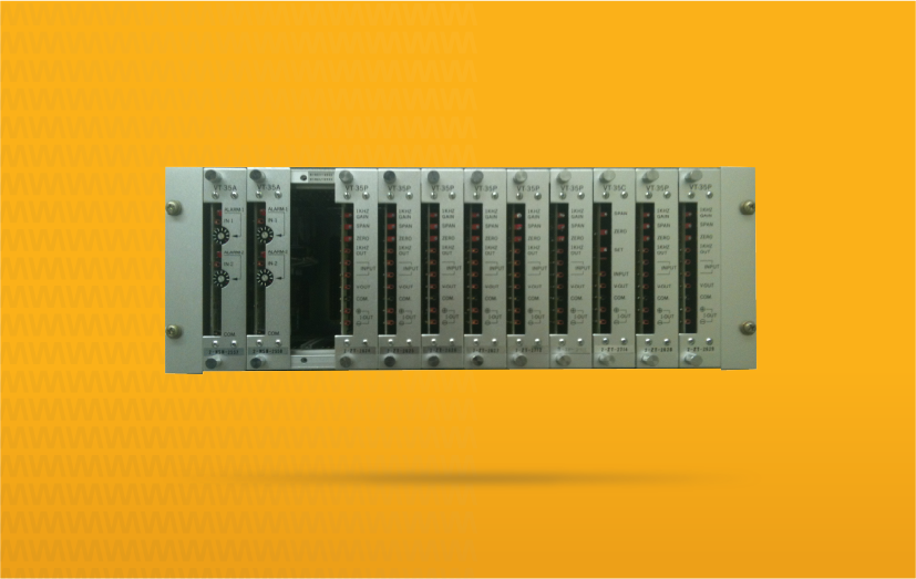
Figure 2: A Hitachi TSI system installed in the mid-1980s on a steam turbine generating plant in Canada. The form factor is unique to Hitachi and its control system of the era. Notice that there are no buffered output connections.
This is very tight integration because it must physically reside in the same rack, thus using the same backplane and the same backplane communications. This level of integration has largely been abandoned because it becomes obsolete as soon as the underlying control system to which it connects changes form factors.
What we generally find is that users that are not particularly sophisticated in their vibration monitoring practices find it easy to simply trust the control system supplier to supply the entire scope of a project, and it does not matter to them whether the vibration is a stand-alone offering or completely integrated. Vibration to such customers is simply another protection parameter and they are not generally employing vibration monitoring data as part of a more comprehensive machine health program where condition monitoring and other parameters are used to determine when to perform maintenance.
More sophisticated users, however, often demand condition monitoring capabilities and a significant problem with OEM offerings is that they are generally not machine-agnostic. In other words, their offerings are not generally designed to address all types of machines and manufacturers encountered in a typical plant. Users can quickly end up with monitoring system from machine OEM A, another monitoring system from OEM B, still another from OEM C, etc. When it comes time to tie all of these together into a single condition monitoring environment, they often encounter a dead end. Indeed, early “integrated” systems often lacked even buffered outputs of any kind – whether BNC or terminal strip connections – and there was no way to connect condition monitoring without literally tapping into the incoming raw transducer signal, creating a vulnerability in the integrity of the signal path. Figure 2 represents a system without any buffered output connections and is thus indicative of this problem: systems without forethought to the need for condition monitoring connectivity. Such systems cannot easily use even a portable data collector connection.
Thus, one of the big problems for users with form-factor integration into a control system platform is that of connectivity to condition monitoring that can be plantwide instead of machine-specific and OEM-specific. Figure 3 shows another such system. Although it has buffered outputs, and indeed connectivity to the manufacturer’s own condition monitoring environment, DCS manufacturers rarely possess the level of subject-matter expertise on vibration and condition monitoring to deliver a system with the capabilities found from suppliers that are more focused strictly on machinery health solutions. Indeed, a problem is that oftentimes a DCS vendor will develop such a system, but then not be able to justify the expense of ongoing enhancements because the product is a sideline rather than core business offering. This has the unfortunate result of leaving users with a system that may be relatively capable when delivered, but not a decade or two later.
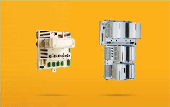
Figure 3: Vibration monitoring module from (left) ABB and (right) Westinghouse (now Emerson), designed for tight integration to their DCS environments and using the same form factor as their other control cards. The module specifically for vibration in the Westinghouse platform is in the lower left. The other modules accommodate non-vibration inputs and the controllers themselves are the two (redundant) modules at the top.
In a few instances, a manufacturer has agreed to develop a card for an OEM’s control system environment. One notable example of this was the 2201 system shown in Figure 4.
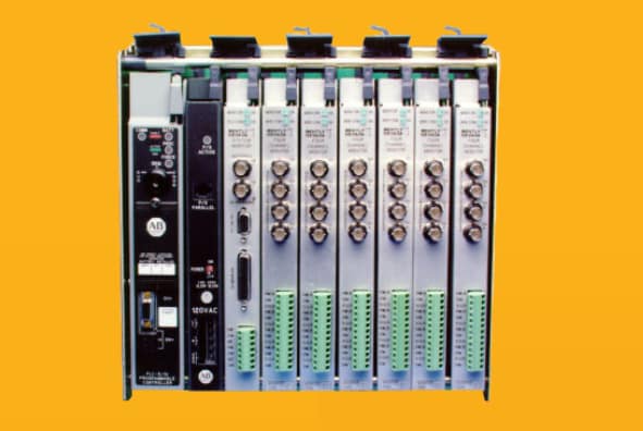
Figure 4: The 2201 system was tightly integrated by using the PLC’s form factor – in this case, the Allen-Bradley 1771. It was developed in the early 1990s and saw primary application as part of Solar® Turbine’s Turbotronic platform, but is now obsolete.
It is now obsolete but was developed in such a way that it had buffered outputs and could be used with the developer’s own condition monitoring environment and thus compatible with its other monitoring systems. Regardless, this level of integration never experienced as much end user interest as did stand-alone systems. Today, as noted earlier, the development of form factor cards for vibration monitoring has largely fallen out of favor.
Remote I/O Integration
A more contemporary approach to tight integration is the use of so-called “remote I/O” (Input/Output) integration. This approach places modules remote from the central processing unit of the PLC or DCS and allows the modules to be placed near the machine. Such an approach has many advantages, not the least of which is reduction of field wiring costs because it links remote I/O together via cables rather than backplanes in chassis. In most cases, the remote I/O is not “dumb” and will embed considerable processing. In fact, it can frequently be thought of as a “rack” but residing on a 35mm DIN rail out in a local enclosure on the machine platform or skid, rather than in a control room cabinet on 19” EIA rails.
Examples of such modules were developed by at least vibration monitoring suppliers over the years and this approach has largely supplanted the development of rack-based cards as the form of integration. In a sense, the backplane is no longer a printed circuit board with connectors. It is a cable using a variety of industrial protocols that may be proprietary or open.
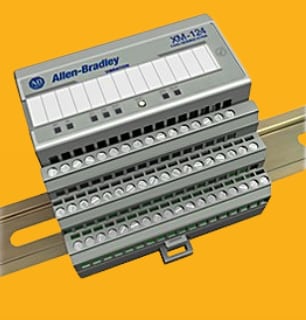
Figure 5: Rockwell’s XM modules were developed so that they could reside remotely from the PLC’s main processor and be mounted on 35mm DIN rail at the machine. Ironically, few were installed in this manner and often were mounted in the same cabinet as the main PLC processor. A communications module (not shown) allowed the modules to communicate over a network using a variety of both open and proprietary communications protocols.
Many of these systems, however, suffered again from connectivity to condition monitoring software and the networks used to connect such modules were (are) often too slow to deliver state-of-the art data acquisition performance. Thus, the user was frequently faced with the trade-off of tight integration that could be mounted on the machine skid to reduce wiring costs, but with condition monitoring capabilities that were not equivalent to those of stand-alone systems. Some, but not all, lacked buffered output connectors – such as the system in Figure 5.
Vibration Transmitters
In the 1970s, so-called “vibration transmitters” were pioneered. Essentially, they made the appeal that a dedicated vibration monitoring system was no longer needed, and the vibration signal could be brought directly into the PLC or DCS as a conventional 4-20mA proportional “process variable” signal. In vibro-meter nomenclature, we refer to this as a “quasi-static” signal because although it can vary to reflect an increase or decrease in vibration amplitude, the signal it is not an instantaneous, complex waveform and thus cannot be used for detailed spectral analysis, orbit analysis, time waveform analysis, or any of the other tools that should be at a condition monitoring practitioner’s disposal. Although it is possible to connect a transmitter to a condition monitoring environment, it is frequently problematic because the buffered signal is either not available, or is at a ground potential shared with the control system and special (expensive) isolation must be used along with signal amplifiers. In practice, the cost to make a transmitter compatible with a condition monitoring environment often exceeds that of a non-transmitter approach. Consequently, transmitters are usually suitable only for machinery that is low-consequence and for which online condition monitoring connectivity is not required.
It should also be noted that a vibration transmitter reduces the complex waveform of vibration to a single attribute: amplitude. This is like taking a complex audio waveform and reducing it to a single attribute: volume. It indeed tells you something about the vibration – and it can be trended – but a considerable amount of information is discarded.
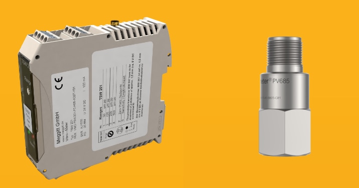
Figure 6: Vibration transmitters convert the signal from a sensing chain to a conventional 4-20mA proportional “process variable” signal, allowing the PLC or DCS to act as the vibration monitor. Some, such as our model TSW 201 (left) utilize an external sensing chain and can thus be used agnostically with any manufacturer’s sensor. Others, such as our model PV685 (right) embed the transmitter functionality directly into the sensor.
As such, vibration transmitters have their place, and indeed are supported within the vibro-meter product line (Figure 6), but should be applied with an understanding of their many constraints. They indeed turn a PLC or DCS into a “vibration monitor” but introduce numerous limitations that are usually only warranted on smaller, less-consequential machines.
API 670
Perhaps the industry’s most recognizable and widely-adopted standard for machinery protection is API 670. Indeed, its very title is “Machine Protection Systems” and it has continued to grow in popularity since first released in 1976 (and now in its 5th edition).
The default assumption in API 670 is that the vibration monitor will be stand-alone and regardless of whether a distributed architecture, centralized architecture, or some level of integration exists, adequate segregation will be provided. Figure 7 is an excerpt from API 670 5th edition and speaks for itself in this regard.
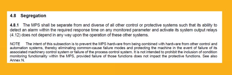
Figure 7: The concept of segregation is fundamental to the requirements of American Petroleum Institute Standard 670 “Machinery Protection Systems”. This means that if a system is integrated with the control system in some fashion, it cannot lose its ability to take protective action in the event the control system itself fails.
Customers, of course, always have the option of taking exception to specific paragraphs within API 670 – or not using it all – but it should be recognized that such recommendations were compiled by the shared experiences of hundreds of end users, machinery OEMs, and monitoring system manufacturers over more than four decades. As such, they reflect good engineering practice.
One implication of API 670 is that if a customer elected to use vibration transmitters and a PLC as the “vibration monitor”, the PLC could not be shared with other protective functions and would have to be dedicated to only the machinery protection / vibration monitoring function. For this reason – and others – transmitter-based systems are rarely used when strict API 670 compliance is necessary.
Safety Instrumented Systems (SISs)
In the early days of SISs, specially designed PLCs were often used with multiple levels of redundancy. It was felt that because transmitters were “simple” devices that had low failure rates, a very reliable approach for machinery protection when part of a safety instrumented loop was to bring the vibration in as a 4-20mA process variable. However, this ignored the fact that an additional component (the transmitter) was being introduced between the sensing chain and the PLC and no matter how small its failure rate, was still non-zero. It also ignored the importance of condition monitoring connectivity as a necessity on the class of most machines that were candidates for safety instrumented functions and thus SIL certification. Lastly, it ignored the fact that most machines for which safety instrumented functions were needed were also of a class for which API 670 compliance is often warranted.
In the early 90s, when standards such as ISA 84.01, IEC 61508, and IEC 61511 were making their debut, considerable interest was shown in treating vibration as a simple 4-20mA input. However, this approach has largely been supplanted by insisting on a vibration monitoring system with SIL certification and using that system’s relays as the basis of protection rather than a 4-20mA signal into the safety PLC. The vibration monitor still often provides an input to the safety PLC, which is responsible for an orderly shutdown of the machine and corresponding process, but the signal is discrete in nature – often from a dry relay contact – rather than as a 4-20mA signal where the PLC must act as the “monitor”.
The Condition Monitoring Challenge
As we have noted, one of the most important questions to ask when it comes to use of a highly integrated vibration monitoring module that resides directly in the control system is what level of condition monitoring connectivity it supports. This consideration also touches vibration transmitters, as previously discussed. Many times, OEMs will develop solutions that cannot be broadly and agnostically applied across the diversity of machines in a typical plant. For example, a pump manufacturer may introduce a wireless sensor and tout its benefits, but upon closer examination, it is not suitable for other types of machines, cannot easily integrate into a more generalized condition monitoring ecosystem, and cannot be easily used by the end user and instead part of a long-term warranty solution offered by the machine OEM who assumes that they will be the primary user of the data rather than the end user.
Suffice to say that most customers find that they want a single, over-arching umbrella in their condition monitoring software that can connect numerous devices together, regardless of machine type, machine manufacturer, or machine control platform. Tightly integrated systems based on a machine OEM’s (or PLC/DCS supplier’s) platform will often be deficient in this regard.
Centralized versus Distributed Considerations
A frequent criticism of centralized, rack-based architectures is that they do not often address the needs of machine packagers that want to place the instrumentation on the machine skid, and thereby reduce wiring costs. When one considers the historical context for this, it makes sense. Assume that you have a machine with 300 points of instrumentation I/O. Suction pressure, discharge pressure, lube oil temperature, vibration readings from a dozen or more points, and many, many others. In the old days, this meant placing the machine skid at site and then tediously running, terminating, and loop testing 300 individual wires from the skid to the control system location some distance away.
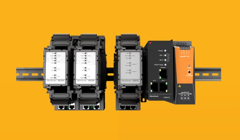
Figure 8: Our VibroSmart series is an example of a distributed architecture that can be tightly integrated with the control system while residing on the machine skid to reduce wiring costs.
By placing the monitoring system on the skid, and allowing its components to be distributed, and using a similar approach for each and every measurement – whether pressure, flow, temperature, level, vibration, or any other – the systems can be joined by a common digital protocol, and then run to the control system using perhaps two fiber-optic communication cables for redundancy. Placing the machine at site now becomes an exercise in connecting two cables instead of 300 individual lengths of conventional multi-core copper. What took days could suddenly take less than a day.
The vibro-meter VibroSmart architecture was designed for precisely this type of scenario and is appealing to machine packagers for this reason. One of our guiding design philosophies with the VibroSmart series was to ensure that both our centralized platform (VM600Mk2) and our distributed platform (VibroSmart) offered the same functionality, allowing customers to choose the form fact they needed without concern about large discrepancies in available channel types, features, or functions. This is not necessarily the case with distributed architecture offerings from others; often, they contain reduced feature sets, channel types, and other limitations that make them suitable only for a small sub-class of machines rather than broadly applicable.
For many customers, however, a new monitoring system replaces an old one and the wiring has already been run. A centralized architecture makes the most sense in these instances and our VM600Mk2 becomes an excellent fit.
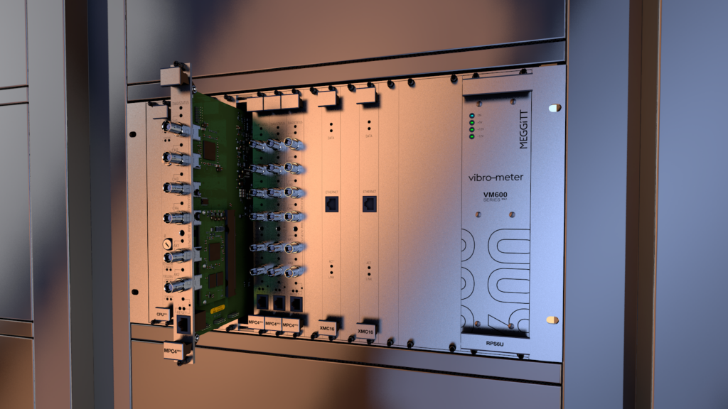
Figure 9: Our VM600Mk2 is the 2nd generation of our highly successful VM600 platform. It incorporates a conventional centralized, rack-based architecture and offers the same integration capabilities as our VibroSmart series.
You can learn more about both our VM600Mk2 and VibroSmart offerings by visiting their respective product landing pages. You may also find our article describing the benefits of distributed systems to be informative. Although it focuses on hydro applications, it is universally applicable to non-hydro applications, too. We also recommend this companion article describing best practices for integration.
Summary
Will the stand-alone vibration monitor truly fade from the scene in favor of systems that are indistinguishable from the control system and represent just another module type in the catalogue? As we have shown, this is unlikely for a variety of reasons. The need for physical integration becomes far less important when protocol integration exists. Furthermore, the highly specialized nature of vibration monitoring means that a supplier with deep knowledge and expertise can be trusted to deliver the necessary functionality, to continually enhance it, and to provide connectivity to plantwide and enterprise-wide condition monitoring solution that can be used across machine types and machine suppliers.
[1] The exact words used by Twain are often misquoted but the meaning is clear. https://www.mentalfloss.com/article/562400/reports-mark-twains-quote-about-mark-twains-death-are-greatly-exaggerated