
Although valves are non-rotating mechanical assets, they can still sustain damaging vibrations and incur other problems. Monitoring their condition is important – particularly on the large valves used in nuclear steam turbine service. In this second and final installment of a 2-part series, we wrap up our discussion by explaining what types of valves are typically monitored along with how they are monitored.
[Editor’s Note: Tables and Figures are numbered sequentially, beginning with part 1. Thus, this article starts with Figure 2 and Table 2. However, footnote numbering starts over again for part 2.]
In part 1, we explained why valves are monitored – covering both the conditions that lead to valve failures and the economic repercussions. We also briefly discussed the benefits of combining the valve condition measurements with the rest of the TSI system. We continue now in part 2 with an examination of the valves used with steam turbines, whether in nuclear or non-nuclear service. We then conclude the discussion with a deeper look at how valves are monitored in our solution and what parameters are used.
Steam turbines employ several types of valves as steam flows from its source1 to the turbine’s admission points (nozzle block), then through the turbine case(s), then through any intermediate reheating and/or moisture removal between cases, and finally to the turbine exhaust2. The spent steam is then recycled back to its source and the heating process begins again.
As the steam flows through this loop, it encounters numerous valves along the way as summarized in Table 2.
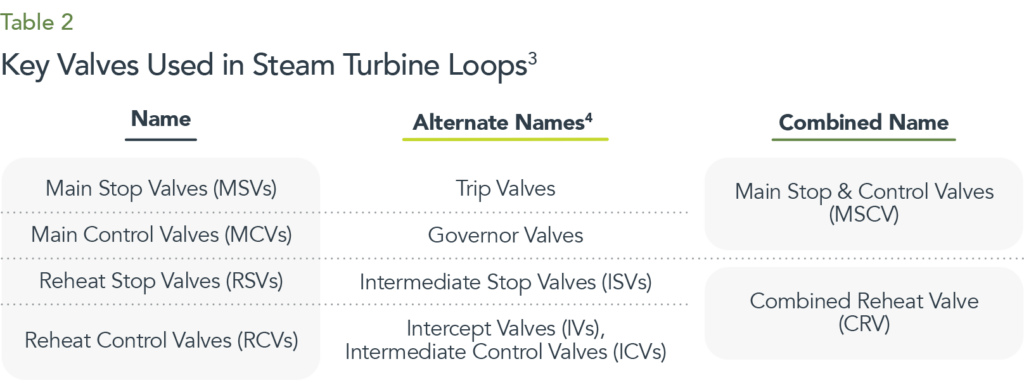
These valves are shown with a typical steam turbine in Figure 2. Each valve and its function is briefly described next.
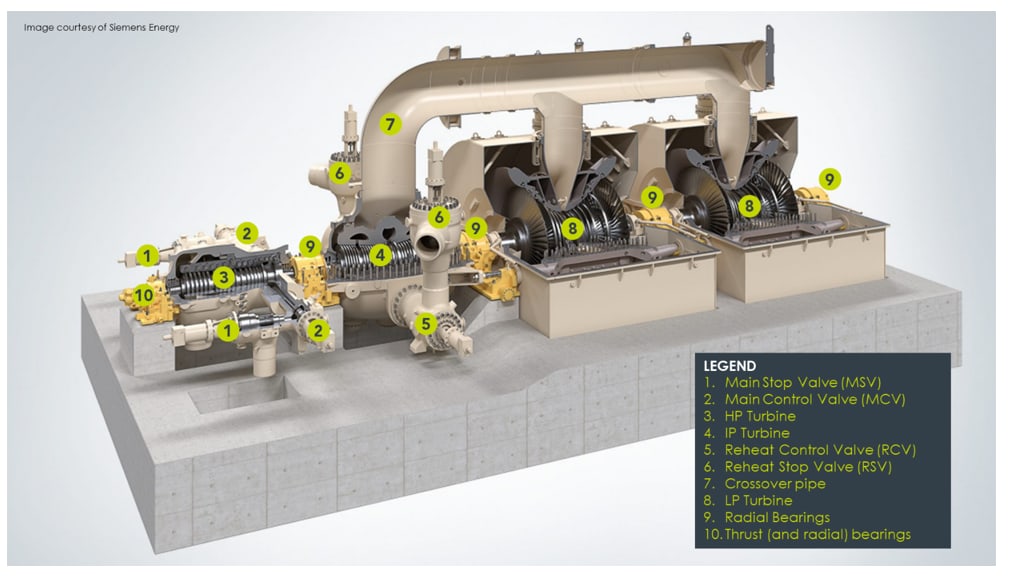
Figure 2. A Siemens SST-6000 steam turbine generator showing stop valves, governing (control) valves, and other key components. Although the valve quantities and arrangements depicted here are typical, they are by no means the only arrangements encountered in practice3. The Main Steam Isolation Valve (MSIV) is not shown but is upstream of the two MSVs. This particular turbine has an HP case, an IP case, and two LP cases and is designed for use in conventional fossil-fired plants. Many older nuclear trains omit the IP section and have only HP and LP turbines while newer designs from some manufacturers combine the HP and IP sections into a single case. The very largest nuclear trains will have three and sometimes even four LP cases.
MSVs are used to isolate a turbine from its source of steam and these valves must be capable of acting very quickly as emergency trip devices. They are usually hydraulically operated and designed with pre-loaded spring forces so the valve will slam shut almost instantaneously (typically 300 ms or less) when hydraulic pressure from the control oil is removed. The most common situation in which an MSV must close rapidly is under overspeed conditions to prevent runaway turbine acceleration and the ensuing catastrophic results. Figure 3 shows a typical MSV. MSVs almost always occur in pairs. This is because the steam flow is so substantial that a single, large valve is not practical but a benefit of having dual valves is that they can be tested through partial stroking without taking the turbine offline.
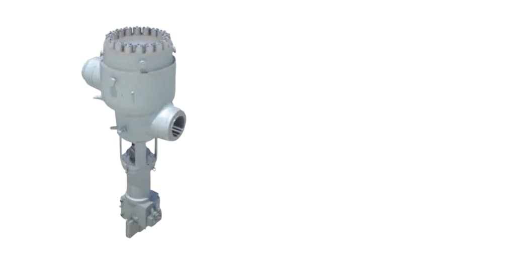
Figure 3. Main Stop Valve (MSV). The hydraulic actuator mechanism is on the bottom and holds the valve fully open except under turbine startup when it acts as a throttle and can assume partially open conditions. During trip conditions, the valve must quickly assume a fully shut condition.
Testing is done to ensure the valve stem is not completely frozen or exhibiting stiction5. Test intervals are typically daily because the consequences of being unable to close these valves would generally mean destruction of the turbine. When these valves are properly monitored, testing intervals can be less often (such as weekly) and this alone can be a substantial aspect of the ROI.
Frequently, the MSVs are physically joined to their companion MCVs as part of the same mechanical assembly, but it is important to note that they remain two separate valves – not a combined valve performing both trip and control functions. The entire assembly is sometimes referred to as the MSCV (Main Stop & Control Valves). A typical MSCV is shown in Figure 4. Although it is common to have two stop valves and four control valves as shown in Figure 4, this is not the only arrangement found in practice and is shown here merely for illustrative purposes.
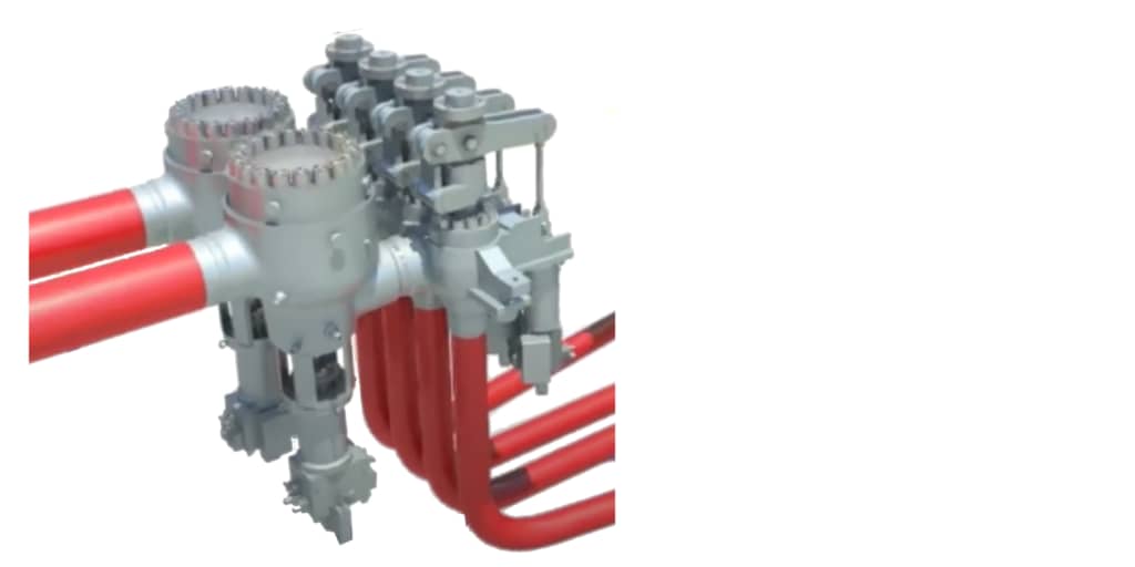
Figure 4. When the Main Stop Valves are joined to the block containing the Main Control Valves, the assembly is referred to as an MSCV. Here, the two steam lines are shown entering the Main Stop Valves which are connected to a block containing four Main Control Valves. The steam exits the four MCVs along four separate lines where it is routed to the HP turbine.
It is also important to note that MSVs are not truly redundant in the sense that a single MSV can stop the turbine. Both must operate in tandem to shut off all steam flow to the turbine and this underscores why daily testing is considered a necessity unless the valves are monitored and can thus be tested at weekly intervals.
Lastly, although the MSVs will be fully open once a turbine is operating above so-called “minimum governor speed”, this is not true while the turbine is being started. During startup, the MCVs are fully open and the MSVs act as throttle valves6 (partially open) to bring the turbine from a standstill up to its minimum governor speed. Upon reaching minimum governor speed, the situation flips: the MSVs become fully opened and the MCVs now become partially open and assume all speed control.
MCVs are used to precisely control the flow of steam through the turbine and thus regulate speed under varying load conditions. These valves are sometimes called governor valves because they are the primary final control element used by the turbine speed control system. There are usually four MCVs per turbine but some applications can have as many as six or seven while new designs may have a single control valve for each corresponding stop valve as depicted in Figure 2. Figure 5 isolates the four MCVs of Figure 4.
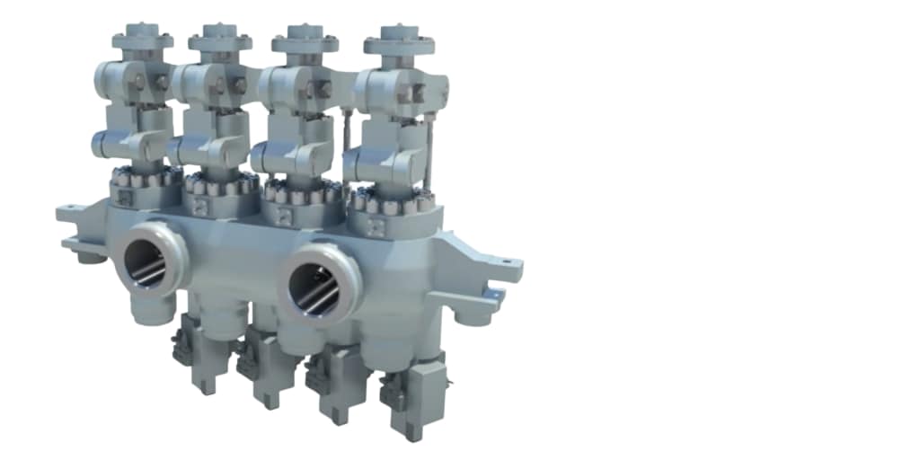
Figure 5. Block containing four MCVs, showing ports that connect to two MSVs.
Each MCV generally admits steam along a portion of the turbine nozzle block. For example, if there are 4 MCVs, each valve will admit steam along a 90 degree radial arc of nozzles; if there are 6 MCVs, each will admit steam along a 60 degree radial arc. When starting a turbine, it is important that everything be heated uniformly and to accomplish this, so-called “full arc admission” is used whereby steam is introduced to every part of the nozzle block and not just a single radial segment (known as "partial arc admission"). Full arc admission is generally accomplished by having the MSVs partially open and the MCVs fully open.
In nuclear plants, the reheater is used to replenish lost energy after the steam exits the HP case and before it enters the LP cases. In fossil-fired plants, reheating of the steam is typically performed between the HP and IP cases, (Figure 2) but additional steam reheating can sometimes be done between the IP and LP cases. Older designs used separate Reheat Stop Valves and Intercept Valves, performing functions analogous to the MSVs and MCVs. However, it is more common in recent turbine and plant designs to combine these functions into a single valve called a Combined Reheat Valve.
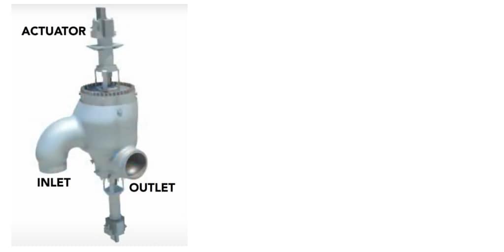
Figure 6. A Combined Reheat Valve (CRV).
Under a turbine trip, not only must the MSVs close, but also the CRVs. This ensures that any of the steam already in the HP case of the turbine and the reheater can no longer expand through the IP and/or LP turbines cases. The steam entrained in those components, along with the intervening piping, can be appreciable and easily cause an overspeed event if allowed to expand through the machine during loss-of-load conditions.
A Note About Steam…
The limitations of nuclear reactor thermodynamics mean that steam is cooler and wetter than in a conventional thermal or combined cycle plant where the boiler or Heat Recovery Steam Generator (HRSG) can elevate steam to much higher pressures and temperatures – so-called “superheated” conditions. The wetter, cooler, lower-pressure steam of nuclear plants means that the turbines must be larger to be economically viable in extracting all the available energy entrained in the steam. Thus, the turbines are rarely smaller than 900MW is size. This entails the so-called LSBs (Last Stage Blades) on the low-pressure cases of steam turbines in nuclear service to be very large in diameter – some nearing 7 meters. Nuclear steam turbines almost always run at half of line frequency and use 4-pole rather than 2-pole generators. Thus, a machine generating 50 Hz electricity will run at 1500 rpm. This also means that the steam mass flow in nuclear plants is larger and the valves are thus larger.
The emergence of SMRs (Small Modular Reactors) is changing this constraint on turbine and valve size, however. SMRs allow turbines as small as 5MWe up to several hundred MWe to be viable. Typical sizes are 80-470 MWe meaning the steam turbines are utility-scale in size and thus still incorporate conventional TSI measurements as well as valves large enough to warrant condition monitoring.
First, it is important that we clarify the distinction between valve condition monitoring and that of valve position monitoring. Valve position measurements are simply to let the control system (and operators) know what position the valves are in, usually in terms of percent open or percent closed. This position is used as part of closed-loop feedback control to properly position the valve and thereby control speed over varying load and steam conditions. Although it was at one time common to include valve position measurements in the same TSI system as bearing vibration, differential expansion, case expansion, rotor eccentricity, etc., it has been more common in the last several decades to bring valve position measurements directly into the distributed control system (DCS). Valve position measurements are quasi-static in nature and typically entail a 4-20mA process variable signal from the sensor measuring valve position (often an LVDT).
Valve condition monitoring is different and involves data that is dynamic in nature, such as from an accelerometer. As such, the system measuring vibration and other TSI parameters is the right home for valve condition. Lastly, it should be noted that valve position can be highly useful as part of the valve condition monitoring system, so the position signal may be shared between the control system and the condition monitoring system. As can be imagined, knowing the precise position of the valve when certain vibrations are occurring is helpful as well as to know particular positions of travel in which problems such as stiction may be occurring. Valve position is also important in understanding hysteresis effects (Figure 7) where mechanical tolerances begin to open in the valve and the ability to precisely position it degrades.
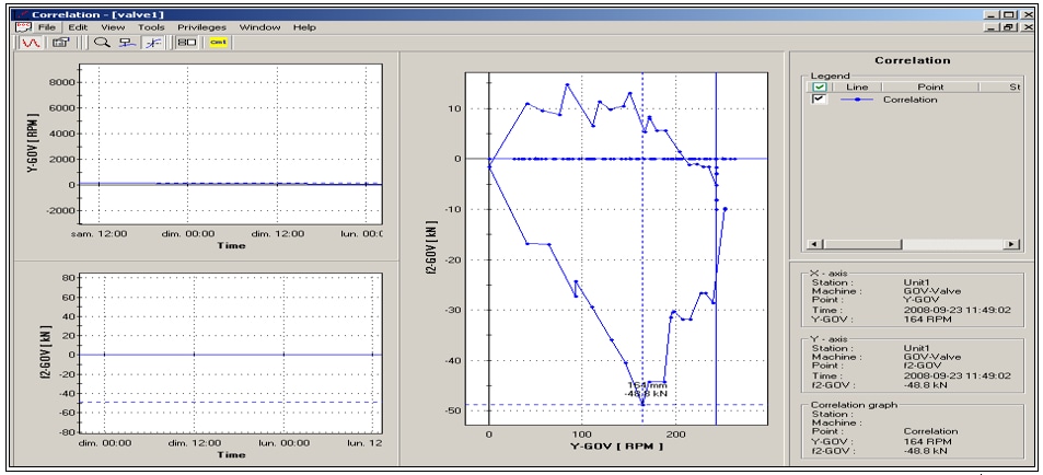
Figure 7. A valve hysteresis plot is available in our valve condition monitoring solution along with many other quasi-static and dynamic plot types useful for trending, diagnosing, and alarming on deteriorating valve conditions as well as operating conditions that can damage the valve and contribute to premature wear.
There are two primary valve conditions monitored in our solution as follows:
VTE is the amount of motive force that is required to move the valve as its condition deteriorates. To move the valve stem, the actuator must overcome the spring force of the valve, the force exerted by steam, and other forces such as static friction between stem and packing. The hydraulic pressure exerted by the servomotor to actuate the valve must overcome all of these forces combined. Thus, using a pressure sensor to measure the pressure exerted by the servomotor becomes a proxy for this force. Plotting this versus the travel position of the valve is invaluable, and indeed the ability to correlate/plot valve travel position against most other parameters in the valve monitoring strategy is vital.
VSV is measured by accelerometers mounted in the axial and radial directions for the valve stem. Axial is the direction in which the stem travels while radial is perpendicular to the direction of stem travel. Both measurements are important in understanding valve condition. As the packing degrades, for example, clearances will open and the stem will vibrate more as well as allowing more steam to leak and build up deposits on the stem. But induced vibrations from acoustic effects of flow can be especially damaging and must be monitored.
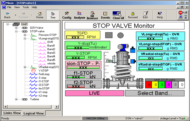
Figure 8. A valve mimic display for a turbine stop valve showing valve travel, relevant forces, stem radial vibration, and stem axial vibration. The vibration within specific frequency bands can be viewed, trended, and alarmed along with overall vibration amplitude from each sensor.
As was noted earlier, vibration of the valve can be induced by the structural coupling of the valve to its corresponding turbine and surrounding machines. However, it can also be flow-induced where acoustic emissions can cause the valve to vibrate and even interact with the structural vibrations in sympathetic fashion to create undesirable resonances. Monitoring these vibrations as simply overall RMS values is not sufficient for diagnostic purposes and it is instead desirable to decompose the vibration into specific frequency bands so that each can be trended and alarmed on if desired. Some characteristic vibration frequencies may give large increases within a specific spectral band without necessarily giving a large increase in the overall vibration amplitude. Thus, the system is capable of alarming on the overall RMS values as well as those within specific, user-configurable frequency bands that are specific to the valve and the steam conditions. Typically, baseline conditions for a healthy valve are captured and stored, and alarming is established based on deviation from these baseline levels. This approach is used for both VTE and VSV.
Our solution is based on vibration, position, and pressure data acquisition in VM600Mk2 hardware and then trending, analysis, and display in VibroSight software, augmented by our Diagnostic Rule Box (DRB) software, a component of the VibroSight suite.
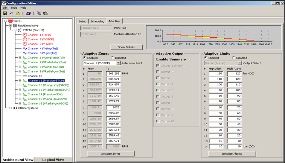
Figure 9. Configuration screen from our valve condition monitoring solution showing how multiple frequency bands can be established from each VSV accelerometer to provide highly adaptive alarming that characterizes particular operating regions.
The system can accommodate up to 10 separate frequency bands for trending and alarming of VSV. It is also capable of capturing very high-speed data during upset conditions, such as when a stop valve closes suddenly during a trip. This level of travel is not observable under normal circumstances because trip valves cannot be closed without tripping the machine – they can only be partially stroked as part of routine testing that may occur daily, weekly, or at other intervals. The ability to precisely see valve parameters over a period that may be as short as only several hundred milliseconds becomes important and a system with these capabilities is desirable.
The stop valves and governor valves associated with both primary steam admission and reheated steam admission between turbine cases are extremely important mechanical assets in conventional thermal plants, combined cycle plants, and nuclear plants. Those in nuclear plants are particularly important given their size and the consequences of not being able to stop or control a turbine properly.
Considerable attention began to be focused on valves in the 1980s based on data collected by EPRI and the NRC showing valve issues were responsible for billions of dollars in lost production each year. Initial efforts focused on preventive maintenance practices, but these were supplanted by condition-based (i.e., predictive maintenance) approaches and online monitoring systems and technologies began appearing as a result during the 1990s and continuing to the present day.
There are many advantages to including the valve condition monitoring system in the TSI system for the turbine, and both capabilities are thus available with our VM600Mk2 monitoring hardware coupled with our VibroSight software suite.
Our vibro-meter products are being used to provide such capabilities at numerous nuclear plants around the world and we work closely with a major OEM to precisely implement their valve monitoring specification while also augmenting it with many additional capabilities that go above and beyond the specification’s base requirements. The system is highly flexible and thus can be adapted to other OEM valve designs and specifications as well.
If you would like to learn more about this solution, as well as our entire suite of products designed for conventional and nuclear power plants employing steam turbines, we invite you to connect with your nearest vibro-meter sales professional, submit an online inquiry, and/or visit our relevant application pages.
1 In a conventional fossil fuel plant, this is a boiler. In a combined cycle plant, the boiler uses waste heat from the gas turbine(s) and is referred to as a Heat Recovery Steam Generator (HRSG). In a geothermal plant, the steam may come directly from a geothermal well. In a nuclear plant, the ultimate source of heat is the reactor vessel, but the steam may be generated directly in the reactor vessel (BWR process) or indirectly in separate steam generator vessels (PWR process).
2 This assumes the turbine is in pure power generation service and steam is not being extracted between stages to use as part of a process plant.
3 You can read more about one particular arrangement of valves, turbines, and moisture separator reheaters (MSRs) in “Westinghouse Technology Systems Manual: Section 7.3 - Westinghouse Turbine and Auxiliaries” available for download from the NRC website https://www.nrc.gov/docs/ML1122/ML11223A247.pdf (retrieved Feb 13, 2023)
4 This list of alternate valve nomenclature used with steam turbines is not exhaustive.
5 See part 1 for a description of stiction along with valuable tutorial references on this topic.
6 For this reason, MSVs are sometimes called “Trip & Throttle Valves” (T&Ts). However, this nomenclature is rarely used with large steam turbines, particularly those in nuclear service.
Many thanks to Rich Kamphaus of Woodward, Inc. (woodward.com) and Kevin Roy of Mechanical Dynamics & Analysis LLC (mdaturbines.com) for their valuable contributions to this article.