In this article, we explore the origins of vibration transmitters and the underlying assumptions that led to their development. We also explore how they operate and their limitations. We conclude with a discussion of where and how they can provide value, common pitfalls that can be encountered, and best practices to observe when a transmitter is deemed to be the right solution for a particular machine.
To a process control specialist, many of the measurements they encounter in industrial plants can be captured by a single number: flow, temperature, level, pressure, etc. This is particularly true when the process parameter is not changing instantaneously and is instead something we call a “quasi-static” variable. In other words, although it changes, and isn’t entirely static, it changes relatively slowly compared to something like a raw vibration signal that may have frequency content extending above 10 kHz and is thus more like an audio signal from a microphone.
This is intuitive because although there can indeed be process transients, most process conditions don’t change on the order of milliseconds. It may take many minutes or even hours to fill a large tank, and thus level changes slowly. Flow rates in a pipe may change, but unless studying the dynamics of turbulent flow, the average flow over a few seconds will usually suffice for control purposes. Or perhaps the position of a valve is changing – or a gate to admit water through a dam – but again the position typically doesn’t change dramatically over a few milliseconds. Or we could consider temperature where thermal inertia generally keeps a temperature from changing by more than a few degrees per second – and often much slower. Even pressure measurements – with a few notable exceptions1 – are typically more static in nature than dynamic. Whereas a vibration signal can change in milliseconds, it is rare for a process variable to change must faster than a few times a second, and for process instrumentation to thus require update rates much faster than twice per second.
All of this is to say that process variable measurements – typically using proportional 4-20mA signals – are adequately characterized by instrumentation that deals only with quasi-static signals rather than high-speed waveform signals. Indeed, if a process flow transmitter updates its output every 250 milliseconds, this is typically more than adequate, and the controller – be it a PLC or DCS – that measures the flow and perhaps adjusts the flow via a valve will often not need to scan its inputs more than once per second and update its outputs once per second.
When we consider what a PLC or DCS fundamentally does, we can gain further insight. Closed-loop control means the controller examines its inputs, decides whether the process is already in (or headed toward) a condition that would put it outsi de of the desired condition, and then adjusts outputs accordingly. This is known as regulatory control because it seeks to regulate the process by looking at conditions and working to keep them within established constraints. Outputs from a control system are often to position a valve, but can also be to turn a motor on or off, to adjust the speed of a motor, to change the amount of heat delivered to a vessel to keep the contents at a constant temperature, etc. The measurements taken occur relatively slowly (seconds rather than milliseconds) and the results of those actions occur relatively slowly as well (seconds, minutes, or even hours – but not milliseconds)2.
In this sense, the PLC or DCS is acting as a monitor whereby it constantly monitors the value of its inputs, and then takes some action with its outputs. It is thus not a large step to imagine a device that can characterize the amplitude of a vibration signal, and then use a PLC, DCS, or machine controller to compare this amplitude against alarm setpoints, and either alert operators with a visual / audible indicator, or actually shut the machine down by perhaps closing a fuel valve or opening the circuit by which power flows to an electric motor. Indeed, when one of the companies that pioneered vibration transmitters back in the 1970s was training its salesforce, their rallying cry was “make the PLC the monitor”. The rationale was that the cost of the PLC had already been incurred for controlling the process, and all that was needed to monitor vibration was a vibration transmitter and a spare channel on one of the PLC’s analogue input cards. The machine being monitored likely already had a trip signal coming out of the PLC for measurements like excessive temperature or insufficient flow, and so adding vibration was relatively effortless. Simply drive the trip relay with vibration – not just other protective measurements.
The vibration transmitter thus takes the complex vibration signal of the sensor, and reduces it to a single, scalar value – perhaps the casing velocity in RMS units, or perhaps just the probe gap from an axial proximity probe and thus thrust position on a machine. A fitting analogy might be an audio signal, as shown in Figure 1.
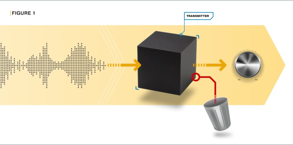
Figure 1: A vibration transmitter can be compared to a black box that ingests a complex waveform (such as an audio signal) and reduces it to a single parameter, such as the overall volume for that segment of audio, or perhaps the tempo (beat per minute). Although either of those can be represented by a single number, they do not characterize all the nuances and information in the raw audio signal. Thus, only one aspect of the original signal is used and the rest is thrown away.
If our only goal is to protect the machine – and not to do any condition monitoring – a strong argument can be made for the use of a transmitter. In such instances, it does not matter if all the nuances of the original waveform have been discarded because we are interested in only a single parameter. In many cases this will be the amplitude. In other cases, it could be the gap from a proximity probe (such as for an axial position measurement). In still other cases it might be that the transmitter is measuring the equivalent of “tempo” from our example in Figure 1 – it is counting pulses in the signal from a proximity probe or perhaps variable reluctance sensor and converting this to a speed measurement. We can successfully use transmitters in such applications and may well be able to save costs because the parameter of interest can be brought into a PLC, DCS, or machine controller and alarm setpoints can be established.
If we use a so-called “loop-powered” transmitter we can reduce the cost even further because we no longer need a separate power source and can use the +24Vdc power that is typically available from controllers analogue input cards. Such cards measure the 4-20mA proportional value provided from the transmitter and compare it against alarm levels the user has programmed. Indeed, some transmitters are even able to detect a problem with themselves or their connected sensor through limited Built-in Self-Test (BIST) capabilities, and when a NOT OK (sensor fault) condition occurs, output a value that is not within the 4-20mA range, such as 2mA. This allows a loss of power or open circuit fault (0 mA) to be distinguished from a sensor fault (2mA), from a valid signal falling in the 4-20mA range.
The Achilles’ Heel of transmitters occurs when the goal is not just machinery protection, but also condition monitoring. This is because the so-called “raw” or “dynamic” signal may be unavailable entirely, or available but with restrictions that make it difficult to use.
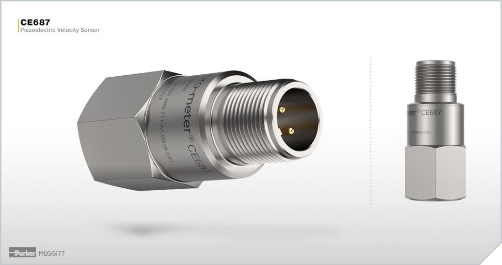
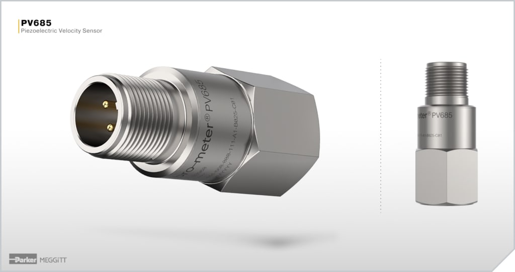
Consider our PV685 and CE687 loop-powered seismic transmitters. The former provides a 4-20mA output proportional to RMS velocity, while the latter provides a 4-20mA output proportional to RMS acceleration. Both are good choices when your goal is to provide basic protection based on either RMS velocity per a standard like ISO 20816, or RMS acceleration for machines that are best measured by a parameter directly proportional to force. The signal is brought into a PLC or other suitable platform, which provides the alarming and shutdown functionality. However, neither sensor provides access to the raw signal and it is assumed that most users interested in condition monitoring will either use a portable data collector to take periodic measurements using a temporary sensor, or will deploy some type of wireless accelerometer technology suitable for online condition monitoring but not protection and use both the transmitter and wireless solution in parallel – one to protect the machine, and the other for detailed health assessment and failure prediction.
Some transmitters do provide a dynamic signal output. However, most transmitters are loop-powered devices and thus are tied to the ground potential of the PLC or other controller that acts as the monitor and transmitter power supply. When using the dynamic signal output, care must be taken that whatever this output is connected to will either have an isolated input, or a floating ground. It is thus usually not a problem when connecting to a battery-powered instrument like a portable data collector (Figure 2), but can be very problematic when connecting to a line-powered instrument, such as one running on AC power from a wall outlet (Figure 3). The line-powered instruments may try to pull the PLC’s ground to its own potential, affecting not only the vibration loop, but possibly all other loops sharing the same ground in the PLC, resulting in false or missed trips, and/or erroneous control actions.
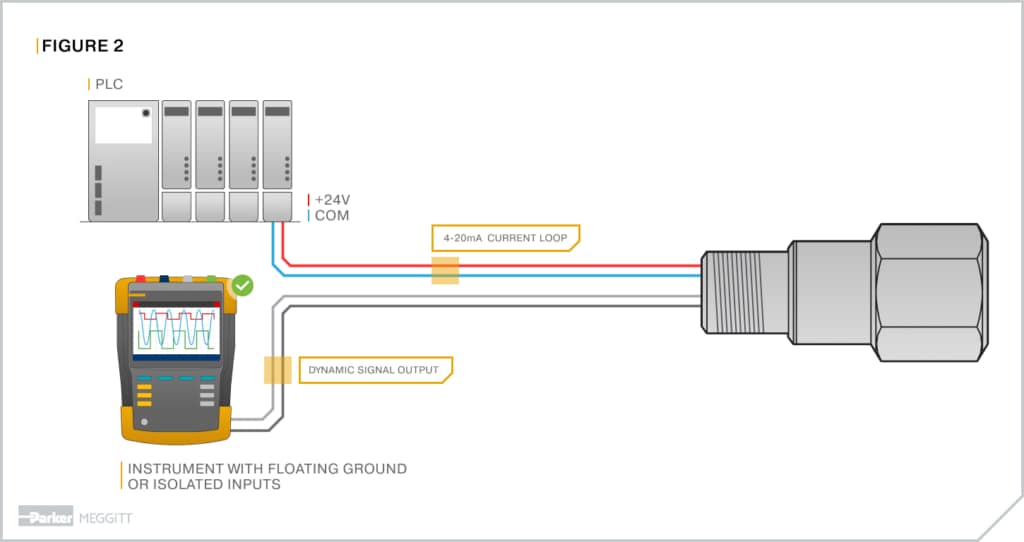
Figure 2: A typical loop-powered vibration transmitter with a dynamic signal output will not generally be problematic when connected to an instrument with a floating or isolated ground, such as a portable battery-powered signal analyzer shown here. It will not attempt to pull the PLC’s COM connection to the instrument’s ground potential and will thus not affect the current loop or potentially other loops in the PLC sharing a common ground.
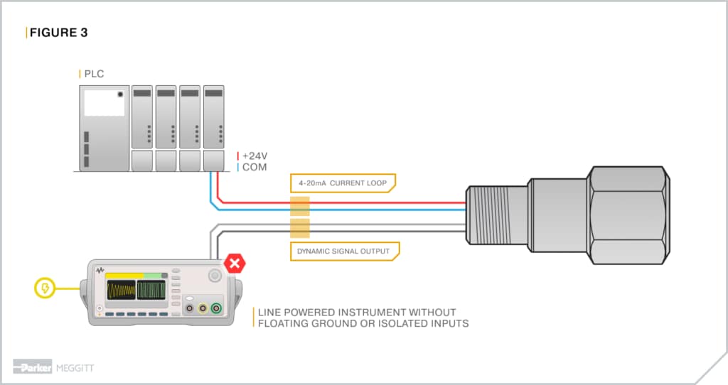
Figure 3: Here, we have connected the transmitter of Figure 2 to a line-powered instrument without an isolated input. It attempts to pull the COM potential at the PLC to its own COM potential, creating problems with not just the vibration transmitter’s current loop, but potentially other loops in the PLC if they also share the same COM. This can result in erroneous readings leading to false or missed trips.
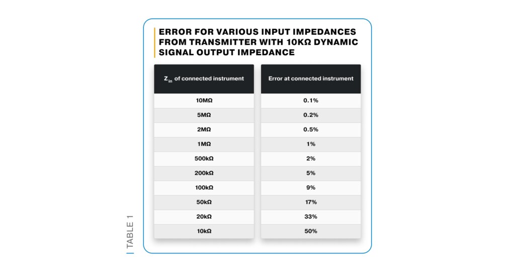
Another common issue is that most portable data collectors have a relatively low input impedance and connection to the dynamic output of a transmitter will affect the reading significantly, compared to a high-impedance input that will usually affect the signal by less than 1%. The error arises because the output impedance of the transmitter’s dynamic signal connections and the input impedance of the connected instrument form a simple voltage divider. If the input impedance of the connected instrument (such as a portable data collector) is not several orders of magnitude larger than the transmitter’s output impedance, the reading at the portable instrument will be unacceptably erroneous. Table 1 summarizes this for a transmitter with a typical output impedance of 10kΩ versus connected instruments with input impedances ranging from 10kΩ to 10MΩ.
Still another issue affecting dynamic signal outputs is that they are often designed to drive only about 3m of cable because the use-case assumptions were for connection to portable equipment – not permanent condition monitoring equipment. It is rare that the condition monitoring apparatus can be mounted within 3 meters of the sensor/transmitter, and thus line amplifiers/isolators become necessary. At some point, such additional items will exceed the cost savings of using a conventional sensor and monitor in the first place, meaning that most transmitters are used in conjunction with only portable data collectors – not online CM systems.
To this point, we have discussed transmitters generically, but the depictions in the figures make it clear that these are transmitters that are also sensors and thus form a self-contained package that is mounted directly on the machine. This makes the transmitter even more convenient because we don’t require a separate signal conditioner. Because the wiring is carrying a proportional current (4-20mA), and without the high-frequency content of a true waveform signal, it can be run considerable distances without concern for signal degradation.
Proximity transmitters are slightly different in that the conversion to 4-20mA occurs in a separate signal conditioner. A good example is our IQS910 (Figure 4) which combines all the functionality of a conventional proximity probe signal conditioner with the additional circuitry needed to detect the raw signal amplitude (or gap in the case of axial position measurements) and output this in a 4-20mA “process variable” format. The device looks exactly like our IQS900 which provides a conventional dynamic signal and requires a monitor. Both devices are SIL-rated and both devices feature TEST and RAW connections that allow the measurement chain to be verified without removing the probe or necessitating use of a dial micrometer or shaker table.
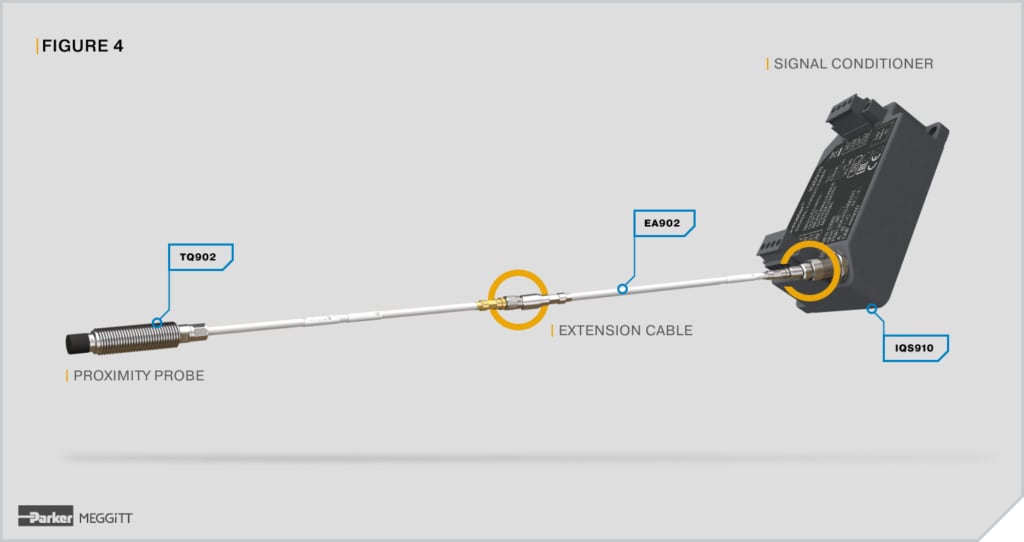
Figure 4: The IQS910 mates to an appropriate proximity probe and extension cable, but provides a 4-20mA output rather than a dynamic signal requiring a conventional monitor. This allows it to be connected directly to a PLC, DCS, or other machine controller, which then serves as the machinery protection monitor. NOTE: The probe and cable in this image have not been drawn to scale.
One class of machines that can especially benefit from a vibration transmitter are small, packaged air compressors. These are so-called “integrally geared” units where a bull gear drives one or more pinions, and each pinion has an impeller. These impellers often run at very high speeds and use fluid-film bearings. While condition monitoring may be a concern, protection is usually the bigger concern due to the speeds incurred. When handling air and packaged onto a skid with its controls, the API standard covering such machines is API Std 672. It is unusual in that, unlike many other API machines, it does not mandate a more full-featured monitoring system such as found in our VM600 or VibroSmart platforms. Instead, it requires only proximity transmitters, and these are usually fed into the control system that is part of the free-standing machinery package. Figure 5 shows a typical integrally geared compressor.
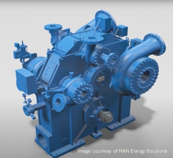
Figure 5: An integrally geared centrifugal compressor. When packaged onto a skid with its controls, and handling air as its working fluid, these are known as API 672-class machines and typically use proximity transmitters as the basis of protection for both radial vibration and axial position. The machine shown here has single, central (bull) gear, and three pinions. Each pinion has two compressor wheels, making this a 6-stage machine. To see an animation of this machine and its internals, click on the image.
Additional machine types can also be good candidates for transmitters – not just API 672-class compressors. Typically, transmitter-worthy machines are less-critical to operations and don’t justify any condition monitoring, or merely off-line condition monitoring using a route-based portable data collector. The key is that the machine would benefit from protection, can be adequately addressed within the limitations of the transmitter3, and a PLC, DCS, or other machine controller is already installed with capacity to add more analog inputs (i.e., 4-20mA signals). There must also typically be additional discrete output channels available in the controller to send the shutdown signal to the machine, thus protecting it. However, when these items are not already present, care should be taken to review the costs, as analog input cards and discrete output modules may eclipse the price savings of using a transmitter. A smaller, modular monitor such as our VibroSmart platform can be a good alternative in such instances.
To learn more about transmitters in general, and specifically about our vibro-meter offerings including the CE687, PV685, and IQS910, contact your nearest sales professional. In addition to the products mentioned, we also offer vibration switches and small 2-channel monitors that may be suitable for balance-of-plant machinery and other situations where a more sophisticated offering such as our VM600 or VibroSmart is not required.