The consequences of a false or missed trip can be enormous on modern turbomachinery. Consider for a moment an ethylene compressor incurring a thrust bearing failure without a reliable trip function. As the bearing destroys itself there is nothing to constrain further axial movement of the rotor assembly. Seals are wiped and ethylene escapes, contacting the hot seal face. A fire and explosion ensue. And yet, the damage is far from over. The rotor continues to move axially, unabated, as rotating and stationary parts now come into contact, and the multi-million-dollar assembly formerly known as a rotor becomes a corncob. The plant is forced to flare. Headlines are generated, making the national news. Fines and lawsuits follow, some pertaining to environmental concerns. Weeks of lost production result. The plant scrambles to locate spare parts and mobilize personnel to effect repairs, which are not confined to the offending machine and have damaged many parts of the process unit. Downstream customers further in the value chain are impacted, too, as a lack of feedstock creates ripple effects. And – only if the plant is exceptionally fortunate – no serious injuries or fatalities occur.
Similar pictures could be painted across multiple industries and machine types. It's no wonder that many operators are insisting on SIL-rated protection loops on an increasing number of machines. We understand this need and are pleased to offer SIL-2 certification in our VM600Mk2 platform, improving on the SIL-1 offered in our original VM600 platform. The certification is available on both our universal “one card does it all” MPC4Mk2 module and our 16-channel RLC16Mk2 relay module1.
Today, the need for SIL is abundant as many customers consider selected vibration, thrust, and other parameters to be a Safety Instrumented Function (SIF) in an effort to reduce risk. Although contrived, the example in the introduction of this article is both sobering and – unfortunately – entirely plausible.
The increased use of instrumentation to reduce risk in the process industries can be traced most notably to the Union Carbide Bhopal disaster in 1984 – widely considered to be the worst industrial accident in history2. The exact death toll can only be estimated but official government estimates exceeds 5,200 people and compensation was paid to more than 570,000 people that sustained injuries. The phrase “never again” reverberated across the process industries and standards such as ISA S84.01, IEC 61508, and IEC 615113 appeared within the following two decades4 as a means of guidance on using instrumentation (Safety Instrumented Systems) to reduce risk. Manufacturers followed suit by developing highly redudant, fault-tolerant architectures and a standardized methodology for quantifying risk reduction by a factor of 10-99(SIL 1), 100-999 (SIL 2), or 1000-9999 (SIL 3)5.
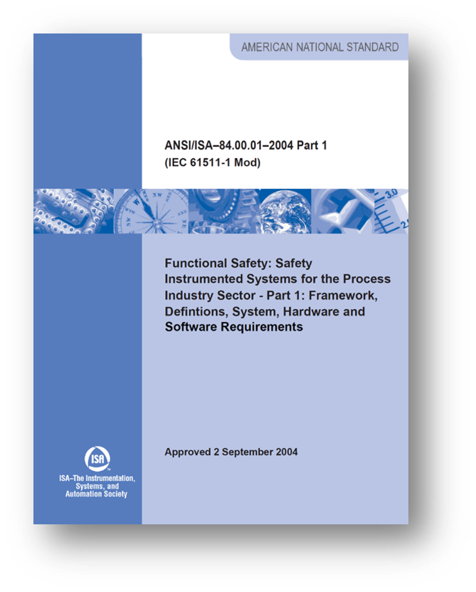
Figure 1: ISA S84.01 was the first standard for the process industry sector dealing with Safety Instrumented Systems (SISs) and was originally published in 1996. IEC 61511 is essentially the internationalized version of S84.01 and was published in 2003.
Originally confined primarily to Programmable Logic Controllers (PLCs) used as Emergency Shutdown (ESD) Systems, the need for field devices that were also SIL-rated became apparent, as well as the need for systems that themselves fed the ESD system. Collectively, these are known as Programmable Electronic Systems (PESs) providing Safety Instrumented Functions (SIFs) with Safety Integrity Level (SIL) certifications. How’s that for a sentence full of acronyms?
The end result, however, is that an instrument loop (one or more measurement chain inputs, a monitor providing associated processing and alarming, and one or more outputs) is only as strong as its weakest link. Thus, if a loop consists of a SIL 3 element (perhaps an interposing relay or final shutdown element like a valve), a SIL 2 element (such as a sensor), and a SIL 1 element (such as a monitoring system), the loop itself will be SIL 1. As simple devices, most sensors are not the limiting factor in a loop’s SIL rating. It is typically the monitor. Likewise, most final control elements are simple devices and can achieve SIL 2 or 3 through redundancy.
In practice, the vast majority of machinery vibration applications where a SIL-rated loop is required are either SIL 1 or SIL 2. In contrast, SIL 3 is common on requirements for overspeed protection loops, as set forth in API 6706.
A false trip (sometimes called a “spurious” trip) can have large economic repercussions because many machines also bring the process to a halt and restarting a process can take many hours and sometimes even a day or more. However, a false trip is rarely a safety concern – it is an economic concern. In the world of safety instrumented systems, the safe state of a machine is always considered to be its stopped condition. Consequently, functional safety necessarily confines itself to missed trips – not false trips.
Using this reasoning, the safest system would utilize n levels of redundancy and 1-out-of-n voting. For example, if three separate shutdown systems were used, they would be three times less likely to miss a trip than if only a simplex (1-out-of-1) approach was used. The problem, of course, is that the systems can also generate a false trip and this too is 3 times as likely under a 1-out-of-3 configuration. We could arbitrarily reduce the likelihood of a missed trip by going to 1-out-of-4, 1-out-of-5, etc., but our probability of a false trip increases as well. As was mentioned, this is rarely acceptable because there are economic repercussions to a false trip.
On the flip side, one could reduce the probability of false trips by employing redundant voting. For example, imagine that we took the same 3 systems assumed earlier, and instead of logical OR voting (1-out-of-3), we employed logical AND voting (3-out-of-3). The likelihood that all 3 systems would fail at the same time to generate a false trip is clearly lower than in a 1-out-of-3 system, but now if even a single one of the three loops malfunctions, we will miss a trip and thus a 3-out-of-3 system is less safe than a 1-out-of-3 system.
To address these simultaneous but competing needs, industry has generally adopted an m-out-of-n approach for achieving functional safety that balances the likelihood of false trips with that of missed trips while achieving the necessary Safety Integrity Level (SIL).
The two modules providing machine shutdown protection in our VM600Mk2 platform are the universally configurable 4-channel MPC4Mk2 monitoring module7 and the 16-channel RLC16Mk2 relay module. The MPC4Mk2 contains its own relays and the necessity for an RLC16Mk2 module thus occurs only when more wiring contacts or more complex voting logic is required than can be accommodated by the four user-configurable alarm relays and single status relay onboard each MPC4Mk2.
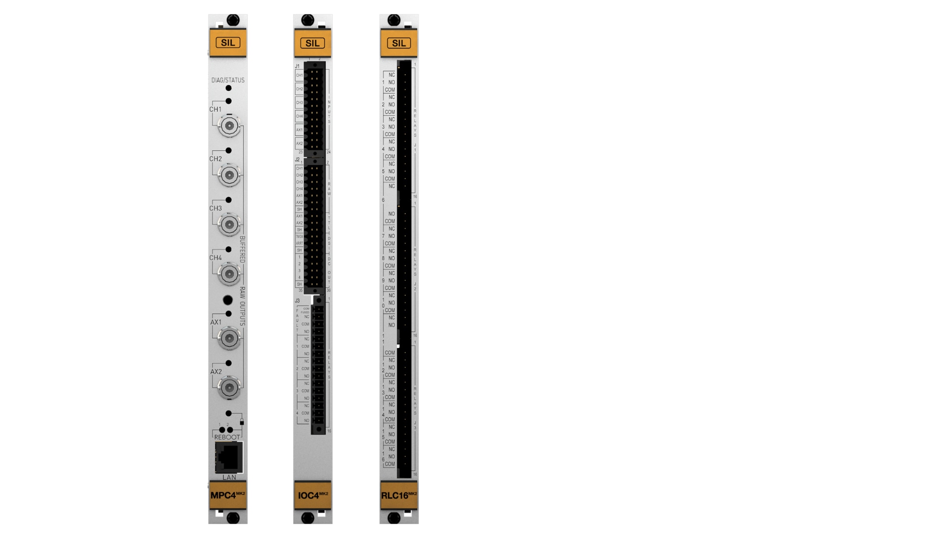
The SIL-rated versions of the MPC4Mk2 (left) and RLC16Mk2 (right) modules are easily distinguished by the use of “safety orange” on the insertion / removal handles. The IOC4Mk2 (middle) also features safety orange pull handles and is the companion I/O module for the MPC4Mk2.
For SIL-rated applications, redundant power supplies are always required.
Because none of the other VM600Mk2 modules form part of the protective functions, SIL rating are not required. This includes the CPUM (used for communications), the XMC16 (combustion condition monitoring), and the XMV16 (vibration condition monitoring).
Both SIL and non-SIL modules can co-exist in the same VM600 rack; SIL-rated systems always require redundant power supplies.
However, with the new MPC4Mk2 modules, the separate condition monitoring modules of the XMV16 are no longer required – the MPC4Mk2 integrates both protective capabilities and condition monitoring capabilities into the same physical module.
Q1: How is SIL 2 achieved? Does it require redundant sensors? Redundant channels? Redundant relays?
A1: SIL 2 requires only a single channel except for those measurements that are intrinsically dual-channel, such as dual case expansion, dual differential expansion, etc. Tracking filters deserve special mention because they require both speed and vibration inputs, but unlike a non-SIL version of the measurement, SIL-rated tracking filters require redundant speed channels8. A SIL-rated tracking filter measurement thus consumes three (3) MPC4Mk2 channels as follows:
1) Vibration channel
2) Speed channel 1
3) Speed channel 2
Q2: How do SIL and non-SIL modules differ from one another? Are they identical except for firmware or are there other differences?
A2: A SIL module contains additional circuitry compared to non-SIL modules, allowing better diagnostic coverage. SIL modules also utilize different firmware than non-SIL modules. For this reason, installations that have a mix of SIL and non-SIL modules must carry two different spares. See also the table below.
Different versions of the VM600Mk2 MPC4Mk2 + IOC4Mk2 (and RLC16Mk2) module
| Standard versions VM600Mk2 MPC4Mk2 + IOC4Mk2 (and RLC16Mk2) | SIL versions VM600Mk2 MPC4Mk2 + IOC4Mk2 SIL (and RLC16Mk2 SIL) |
| Aluminium (silver) front panels (MPC4Mk2 +IOC4Mk2, RLC16Mk2) | Aluminium (silver) front panels with yellow/orange "SIL Safety" labeling (MPC4Mk2 +IOC4Mk2 SIL, RLC16Mk2 SIL) |
| One electronics processing module on MPC4Mk2 for all functionality (measurements, management and interfacing) | Three electronics processing modules on MPC4Mk2 SIL: 2 x processing modules for measurements (with measurement redundancy with cross-checking) 1 x processing module for management and interfacing |
| Separation (firmware only) of machinery protection system (MPS) and condition monitoring system (CMS) functionality/processing on the MPC4Mk2 module | Complete separation (hardware and firmware) of machinery protection system (MPS) and condition monitoring system (CMS) functionality/processing on the MPC4Mk2 SIL module |
| MPC4Mk2+IOC4Mk2 module only runs diagnostics | MPC4Mk2+IOC4Mk2 SIL module and RLC16Mk2 SIL module both runs diagnostics |
| Up to 2 x tachometer (speed) channels | 1 x tachometer (speed) channel only |
| Tachometer (speed) channel signals can be freely shared via the VM600Mk2 / VM600 rack's Tacho bus. Note: MPC4Mk2+IOC4Mk2 module can put signals on and take signals from the Tacho bus | Tachometer (speed) channel signals cannot be as freely shared via the VM600Mk2 / VM600 rack's Tacho bus. Note: MPC4Mk2+IOC4Mk2 SIL module can put signals on but cannnot take signals from the Tacho bus |
| Digital high-pass filter (HPF) cutoff frequency up to 15kHz | Digital high-pass filter (HPF) cutoff frequency up to 400 Hz |
| Up to 4 x user-configurable relays (RL1 to RL4) and 1 x common circuit-fault relay (FAULT). Note: In standard applications, use of the FAULT relay is optional | Up to 4 x user-configurable relays (RL1 to RL4) and 1 x common circuit-fault relay (FAULT). Note: In standard applications, use of the FAULT relay is mandatory |
| Alarms and relays can be configured as latched or not latched | Alarms and relays can be configured as latched or not latched |
| Up to 16 x user-configurable relays (RL1 to RL16) per additional RLC16Mk2 module | Up to 16 x user-configurable relays (RL1 to RL16) per additional RLC16Mk2 module |
| User-configurable relays can be configured as normally energised (NE) or normally de-energised (NDE) | User-configurable relays must be configured as normally energised (NE) |
| Machinery is protected when the MPC4Mk2 module's operational mode is Locked or Unlocked | Machinery is protected only when the MPC4Mk2 SIL module's operational mode is Locked. Note: In safety-related applications, an MPC4Mk2 SIL module can only run in the Locked operational mode. |
| System (MPC4Mk2 + IOC4Mk2 module and any RLC16Mk2 modules) does not enter the safe state (fail-safe mode) if an input channel saturates | System (MPC4Mk2 + IOC4Mk2 SIL module and an RLC16Mk2 SIL modules) enters the safe state (fail-safe mode) if an input channel saturates for more than 1 hour |
| Live insertion and removal of modules (hot-swapping) with automatic reconfiguration is permitted. That is, a replaced MPC4Mk2 module will be auto-configured by its associated IOC4Mk2 module | Live insertion and removal of modules (hot-swapping) with automatic reconfiguration is not permitted. That is, a replaced MPC4Mk2 SIL module will not be auto-configured by its associated IOC4Mk2 SIL module |
| Verification of MPC4Mk2 module's serial number by the VibroSight software | Verification of MPC4Mk2 + IOC4Mk2 SIL module's serial number by the VibroSight software |
| Protection configuration signature not required | Protection configuration signature (SIL system signature) required |
| Enforcing of VM600Mk2 system (MPC4Mk2 + IOC4Mk2 and RLC16Mk2) configuration rules by the VibroSight software | Enforcing of VM600Mk2 SIL system (MPC4Mk2 + IOC4Mk2 SIL and RLC16Mk2 SIL) configuration rules by the VibroSight software |
Q3: Can SIL modules be upgraded in the field with new firmware?
A3: Yes, however there are restrictions because an entire safety loop must be signed off by the responsible parties when changes are made. It is thus not simply a matter of installing new firmware. When new firmware for a non-SIL module is released, it cannot be installed on a SIL module. Conversely, when new firmware for a SIL module is released, the process will generally entail more than simply installing the firmware – it will involve a level of paperwork and sign-offs used by your organization in conjuction with its safety instrumented systems, functions, and loops. These will generally not be unique to the VM600Mk2 and are instead broadly applicable across an organization.
Q4: Although SIL and non-SIL modules can be mixed in the same rack, can SIL and non-SIL channels be mixed within the same SIL-rated module?
A4: Although possible, this is not recommended as a best practice. Once non-SIL measurements are introduced in a SIL module, they become subject to the constraints of the SIL channels in the module. One of the challenges with mixing channels is that it becomes easier to confuse SIL and non-SIL channels when they co-exist in the same module. Thus, activities such as bypassing a channel, changing an alarm setpoint or delay, changing a configuration parameter, etc. requires extra vigilance to ensure the change is made to the non-SIL channel(s) and not the SIL channel(s). The easiest way to avoid possible mistakes is to entirely separate SIL and non-SIL measurements into different modules.
Q5: Within a SIL-rated MPC4Mk2, are there any restrictions on available channel types, or are the same channels available as in the non-SIL version?
A5: The channel types available between the two modules are the same. However, certain channels must be configured differently in their SIL embodiment versus their non-SIL embodiment. Tracking filters are a notable example (see Q1). The safety manual for the VM600Mk2 is the definitive statement on configuration/application limitations and constraints and should be consulted.
Q6: For channel types that require a speed or phase input in addition to a vibration sensor – such as an aeroderviative tracking filter channel – how is this handled and is a SIL-rated solution available?
A6: See our answer to Q1.
Q7: Is there a reason that the CPUM, XMV16, and XMC16 modules do not carry SIL certifications?
A7: These modules are not used for machinery protection – only for communications, vibration condition monitoring, and combustion dynamics feedback to the turbine control system – and thus SIL is not a requirement as these loops do not form part of safety instrumented functions. At such time as customers may potentially impose SIL requirements on measurements such as combustion dynamics9, we will revisit the need for certification of additional module types.
Q8: Are SIL-rated temperature or process variable inputs available in the VM600MK2 platform?
A8: The MPC4Mk2 embodies vibro-meter’s “one card does it all” philosophy and is thus able to accommodate temperature and process variable inputs for SIL-rated applications. Any channel (including the two “auxiliary” channels) on each MPC4Mk2 can be configured to accept proportional DC signals (voltage or current). Process variables are thus directly compatible. Temperature inputs require a temperature transmitter to convert the signal from a thermocouple or RTD to a 4-20mA signal.
Q9: Can speed channels in the VM600MK2 be used for SIL-rated overspeed protection?
A9: No. Speed / phase reference inputs are not designed to be used for overspeed applications – whether SIL-rated or not.
Q10: When an RLC16Mk2 module is used, is there any indication on the front panel about where the module resides?
A10: No. The RLC16Mk2 thus has no corresponding module or special faceplate; it consists only of an I/O module designed for insertion at the rear of the rack. Depending on how relay signals will be shared over the backplane, there is generally considerable flexibility in where the RLC16Mk2 (both SIL and non-SIL versions) can be placed with exception of slot 0 (behind the CPUM). In some cases, the best place for it to reside will be immediately behind an empty front slot in the rack. In other cases, it may make sense for it to occupy an available slot (16) behind the power supply. The Protect software within the VibroSight suite is used to configure the VM600Mk2 and is able to indicate where all modules reside in the rack, including relay modules.
Q11: What is the role of the IOC4Mk2 module and why does it carry SIL certification?
A11: The IOC4Mk2 (input/output card) provides all of the analog-to-digital conversion of incoming sensor signals for the MPC4Mk2 (machine protection card) and is where its wiring lands. Because it handles the signals used for protection, it carries SIL ratings. The actual signal processing, alarm threshold comparison, and other protective functionality occurs within the corresponding MPC4Mk2 module itself. With exception of the RLC16Mk2, all modules in the VM600Mk2 consist of a front panel module and a corresponding I/O module that inserts from the back.
Q12: Is there any difference between a SIL 1 and SIL 2 configuration? Can the system be used to meet either SIL rating?
A12: There is no difference in hardware or configuration between a SIL-1 channel and a SIL-2 channel in the VM600Mk2 system. Thus, when a SIL-1 requirement exists, the SIL-2 rating of the VM600Mk2 can be used to meet (exceed) the requirement.
Q13: What company is being used to provide SIL certification of the VM600Mk2?
A13: We have selected Exida (www.exida.com) for this task. You can read more about SIL certification and SIL concepts in general in this informative presentation called “Understanding the How, Why, and What of a Safety Integrity Level”.
Q14: Can any version of VibroSight Protect be used to configure the new SIL modules?
A14: No. Only version 7.5.1 (July 2024) or later.
Q15: What is the recommended proof test interval?
A15: One (1) year is typical; five (5) years is maximum per the stipulations in our SIL certification.
Q16: Can condition monitoring capabilities co-exist with the protection capabilities of MPC4Mk2 cards that are SIL-rated?
A16: Yes. As noted in Q2, the hardware for SIL-rated cards is different and thereby incorporates self-contained redundancy for protective functions, allowing both improved detection of faults and improved tolerance to faults along the protective signal processing path. Just as with standard MPC4Mk2 cards, integrated protection and condition monitoring can be enabled without the need for separate, dedicated condition monitoring modules such as the XMV16. If the user elects to enable the condition monitoring functionality in SIL-rated MPC4Mk2 modules, this does not affect the SIL rating as this processing is carried out in a completely different portion of the module.
[1] The MPC4Mk2 inserts into the front of a VM600Mk2 chassis and uses a companion I/O module, the IOC4Mk2. Both are SIL-certified. The RLC16Mk2 relay module is likewise SIL-certified, but inserts in the back of a VM600Mk2 chassis and has no corresponding front-panel module.
[2] Mandavilli, A., “The World’s Worst Industrial Disaster is still Unfolding” Atlantic Magazine, July 10, 2018, https://www.theatlantic.com/science/archive/2018/07/the-worlds-worst-industrial-disaster-is-still-unfolding/560726/ Retrieved June 30, 2023.
[3] IEC 61508 also deals with functional safety and safety instrumented systems, but is not industry specific. IEC 61511 is essentially an industry-specific version of 61508, tailored to the process industries. It is also nearly identical to ANSI/ISA S84.01 except that S84.01 contains a grandfathering clause that allows use of older, proven-in-use systems.
[4] ANSI/ISA S84.01 was released in 1996, IEC 61508 in 1998, and IEC 61511 in 2003.
[5] SIL 4 is also defined and provides a risk reduction factor of 10,000-99,999. However, the highest level used in the process industries is SIL 3. A process requiring SIL 4 instrumentation would be considered inherently too unsafe and would be either changed or addressed using other means for assuring safety besides using safety instrumented systems (SISs).
[6] American Petroleum Institute Standard 670, 5th edition (Nov 2014) “Machinery Protection Systems”. Section 8 of this standard specifically pertains to electronic overspeed systems. It is also noteworthy that the 5th edition of the standard reflected new SIL-related content to address the increasing demand for SIL-rated vibration, axial position, and overspeed loops.
[7] The MPC4Mk2 is technically the name given to the module that inserts in the front of the VM600 rack. The companion I/O module, known as the IOC4Mk2, is also SIL-certified and is installed immediately behind its associated MPC4Mk2 module. All field wiring connections terminate on the IOC4Mk2.
[8] Redundancy of speed sensors themselves is not required as part of our SIL certification; only redundancy of the speed input channel is required to ensure adequate diagnostic coverage of problems with speed input signal processing.
[9] The XMC16 is a 16-channel module used for accommodating up to 16 channels of combustion dynamics monitoring in a single rack slot. In situations where SIL-certified combustion dynamics is required, use our SIL-rated MPC4Mk2 module instead. It can provide 4 channels of combustion dynamics monitoring in a single rack slot, and while not as densely populated as an XMC16 module, is able to address applications where a SIL-certified loop is required.